Clean release, phase change thermal interface

a technology of phase change and thermal interface, which is applied in the direction of electrical apparatus construction details, transportation and packaging, chemistry apparatus and processes, etc., can solve the problem that the interface cannot be cleanly released from the component, and achieve the effect of low thermal impedan

Inactive Publication Date: 2002-09-26
PARKER INTANGIBLES LLC
View PDF4 Cites 75 Cited by
  • Summary
  • Abstract
  • Description
  • Claims
  • Application Information

AI Technical Summary

Benefits of technology

0029] FIG. 4 is a cross-sectional view of a representative thermal management assembly wherein the heat sink and interface of FIG. 3 are disposed in heat transfer adjacency with a heat genera

Problems solved by technology

In this regard, as a result of the flow of the phase-change material when the interface is heated to a temperature within t

Method used


Image

  • Clean release, phase change thermal interface
  • Clean release, phase change thermal interface
  • Clean release, phase change thermal interface

Examples


example 1

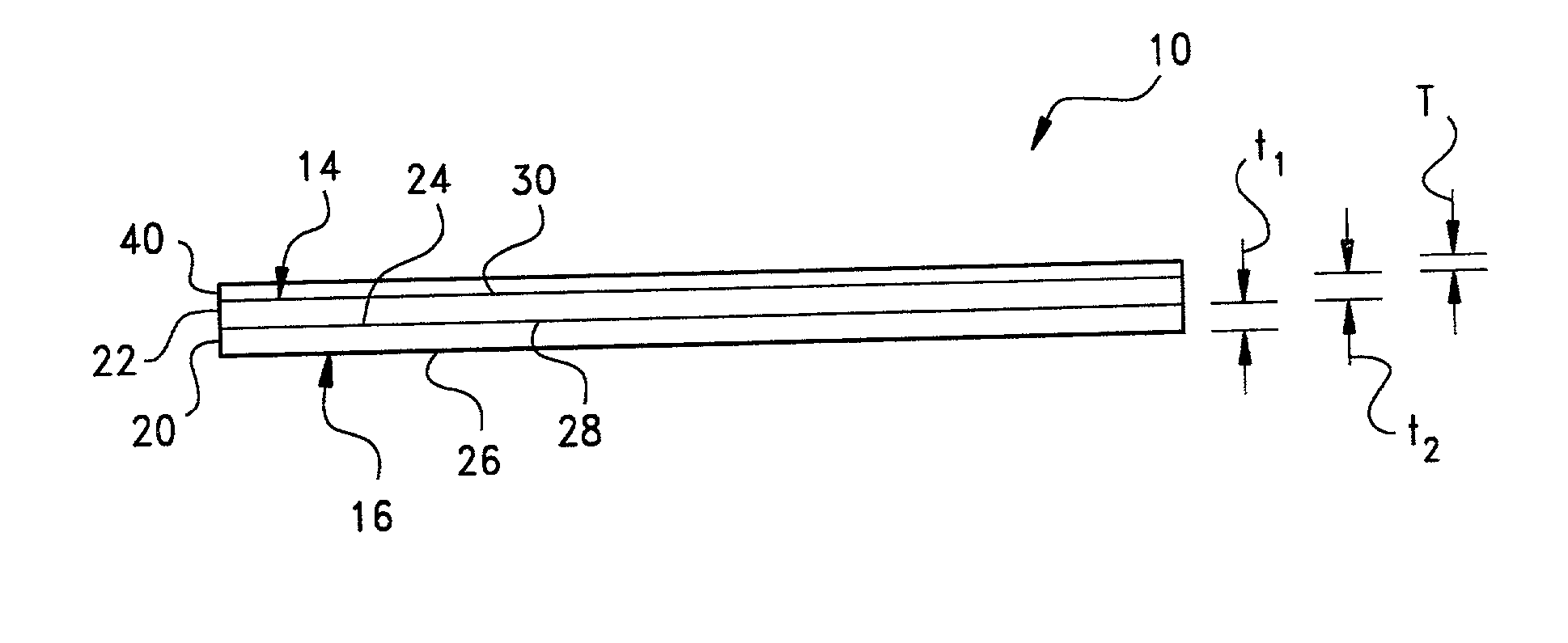
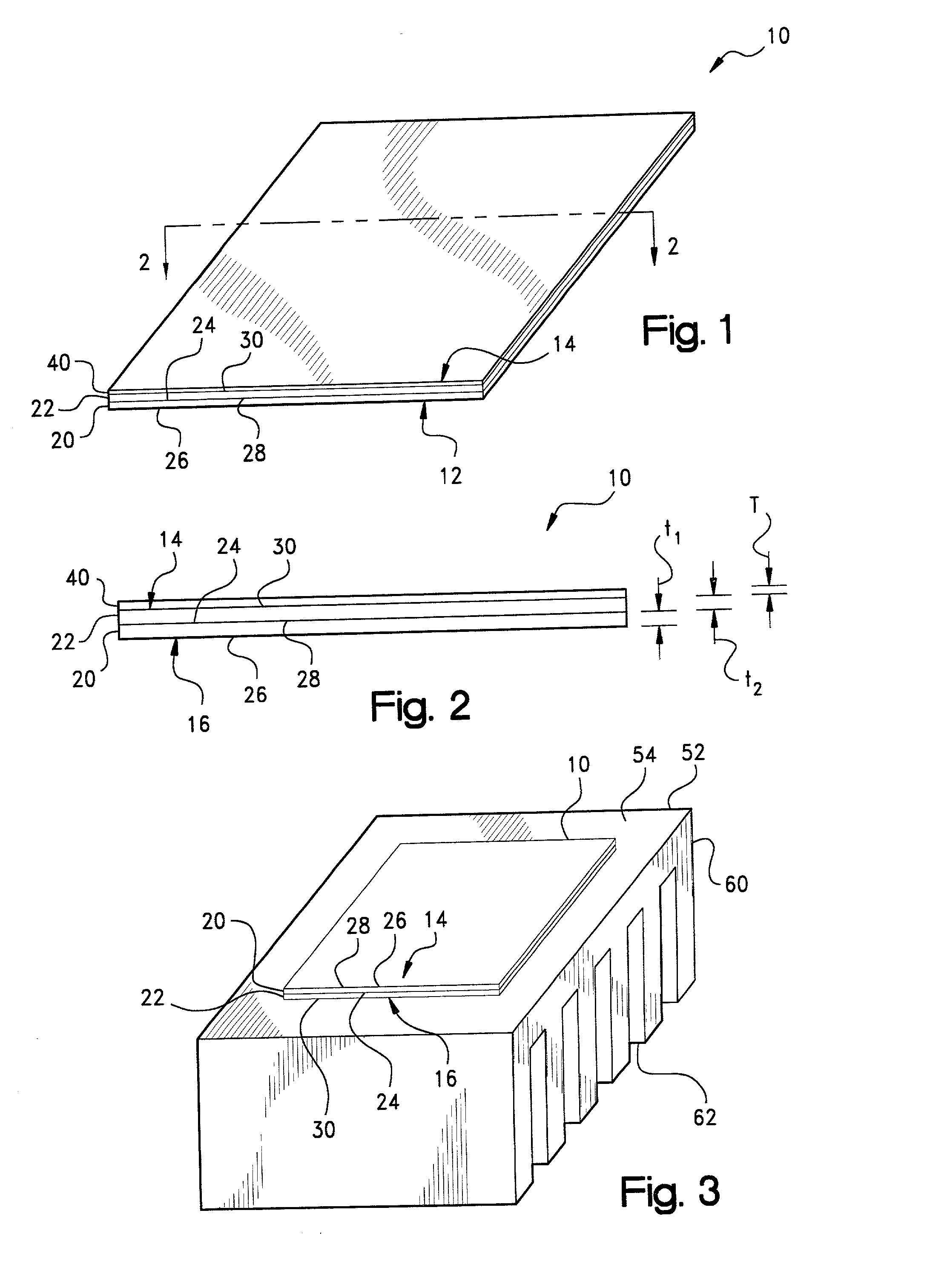
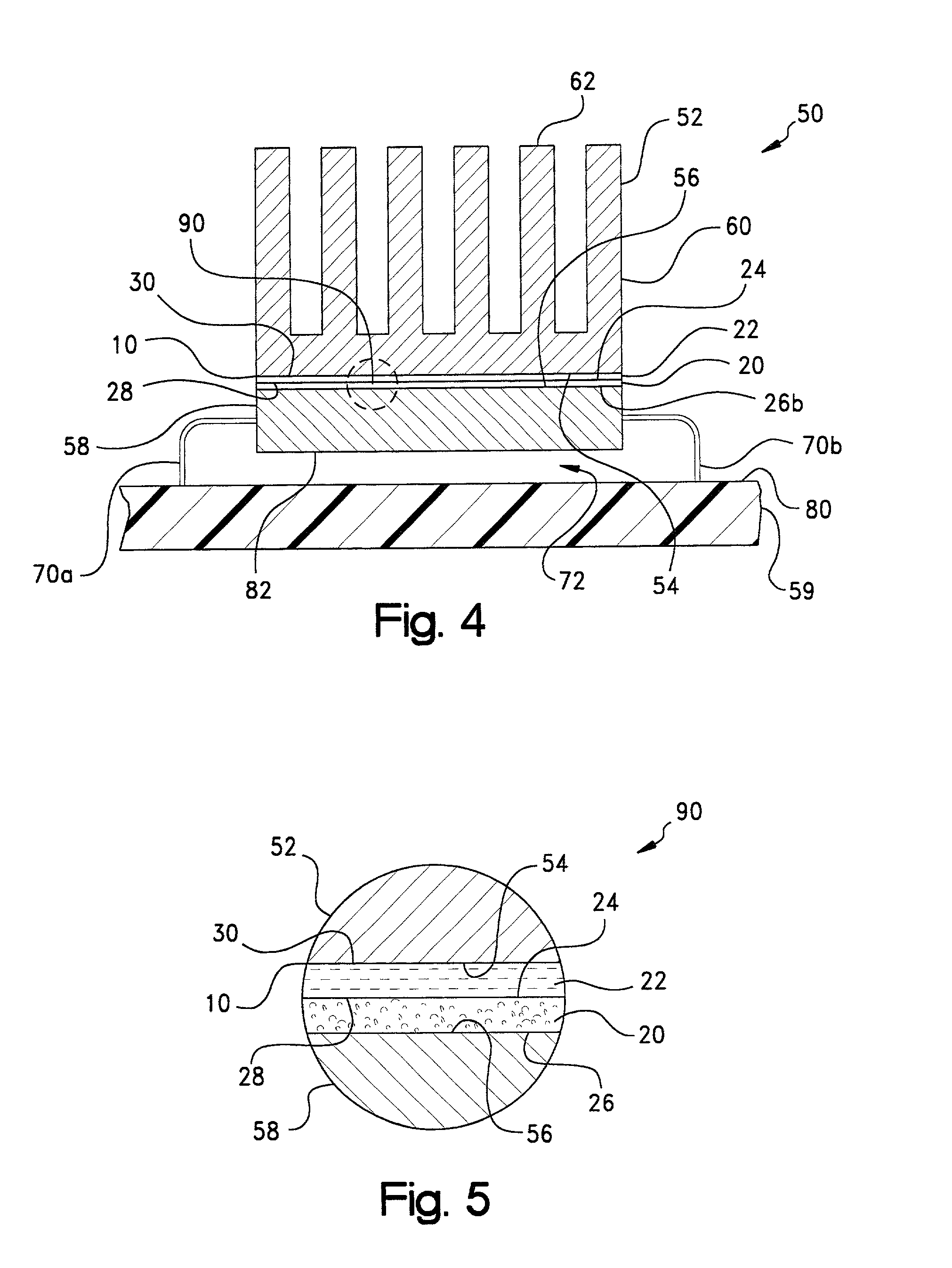
[0064] A 5 mil (125 .mu.m) thick layer of a boron-nitride filled PCM compound (Thermflow.TM. T725, Chomerics TEC Division, Parker Hannifin Corp., Hudson, N.H.) having a phase change temperature of about 58.degree. C., a thermal impedance of about 0.03.degree. C.-in.sup.2 / W (0.18.degree. C.-cm.sup.2 / W) at about 50 psi (350 kPa), and an apparent thermal conductivity of about 0.7 W / m-K was laminated to one surface of a 5 mil (125 .mu.m) thick sheet of a flexible graphite material (Grafoil.RTM. T705, Graftech, Inc., Cleveland, Ohio) having a thermal impedance of about 0.03.degree. C.-in.sup.2 / W (0.18.degree. C.-cm.sup.2 / W) at about 50 psi (350 kPa), and an apparent thermal conductivity of greater than about 7 W / m-K in the "z" or "through sheet" direction.

[0065] The thermal impedance of a sample of the interface material so prepared was determined using a modified ASTM D5470 procedure. A thermal impedance value of 0.091.degree. C.-in.sup.2 / W (0.546.degree. C.-cm.sup.2 / W) was measured whi...

example 2

[0066] A layer of the Thermflow.TM. T725 PCM used in Example 1 was laminated to one surface of a 1 mil (25 .mu.m) thick sheet of a flexible tin foil. The thermal impedance of this laminate was determined using a modified ASTM D5470 procedure. Comparative laminate samples also were prepared by coating the T725 PCM onto varying thickness of aluminum and copper foil, and on the Grafoil.RTM. T705 material used in Example 1. The results are shown in Table 1 below.

1 TABLE 1 Thickness (mils (.mu.m)) Impedance (C-in.sup.2 / W (.degree. C.-cm.sup.2 / W)) Sample PCM Substrate Total 10 psi (70 KPa) 20 psi (140 KPa) Aluminum 5.5 (140) 1 (25) 6.5 (165) 0.19 (1.22) 0.12 (0.77) Aluminum 3.5 (89) 1 (25) 4.5 (114) N / A 0.08 (0.52) Aluminum 9 (229) 1 (25) 10 (254) 0.203 (1.31) 0.125 (0.81) Aluminum 5 (127) 2 (51) 7 (178) N / A 0.16 (1.02) Aluminum 5 (127) 3 (76) 8 (203) N / A 0.18 (1.16) Grafoil .RTM. 5 (127) 3 (76) 8 (203) 0.144 (0.93) 0.087 (0.56) Grafoil .RTM. 5 (127) 5 (127) 10 (254) 0.151 (0.97) 0.12 (0....


PUM

PropertyMeasurementUnit
Percent by massaaaaaaaaaa
Thicknessaaaaaaaaaa
Thicknessaaaaaaaaaa

Abstract

A laminar, thermally-conductive interface interposable intermediate a first heat transfer surface and an opposing second heat transfer surface to provide a thermally-conductive pathway therebetween. The interface includes a first layer formed of a flexible, lamellar graphite or tin foil material, and a second layer formed of a thermally-conductive phase-change material.

Description

CROSS-REFERENCE TO RELATED CASES[0001] The present application claims the benefit of the filing date of U.S. Provisional Application Serial No. 60 / 263,258; filed Jan. 22, 2001 and U.S. Provisional Application Serial No. 60 / 309,552; filed Aug. 2, 2001.[0002] The present invention relates broadly to thermal management materials for electronic devices. Such materials commonly are used as heat transfer interfaces between, for example, the mating heat transfer surfaces of a heat-generating, electronic component, such as an integrated circuit (IC) chip, and a thermal dissipation member, such as a heat sink or spreader, for the conductive cooling of the electronic component. More particularly, the present invention relates to a laminar, thermally-conductive interface which is formed as a laminate of a first layer of a conformable phase-change material and a second layer of a flexible, lamellar graphite material or, alternatively, a tin foil material. The first layer, which may be formulate...

Claims


Application Information

Patent Timeline
IPC IPC(8): H05K7/20H01L23/36H01L23/373H01L23/427
CPCH01L23/373H01L23/3735H01L23/4275H01L2924/3011H01L2924/0002H01L2924/00Y10T428/2857Y10T428/1438Y10T428/2804Y10T428/2813Y10T428/14Y10T428/28Y10T428/1405Y10T428/30Y10T428/31678
Inventor GREENWOOD, ALFRED W.BUNYAN, MICHAEL H.YOUNG, KENT M.WRIGHT, DEANNA J.
Owner PARKER INTANGIBLES LLC
Why Eureka
Try Eureka