
Attachment of a stiff heat spreader for fabricating a cavity down plastic chip carrier

Inactive Publication Date: 2002-10-10
PHOENIX PRECISION TECH CORP
View PDF0 Cites 31 Cited by
  • Summary
  • Abstract
  • Description
  • Claims
  • Application Information

AI Technical Summary

Benefits of technology

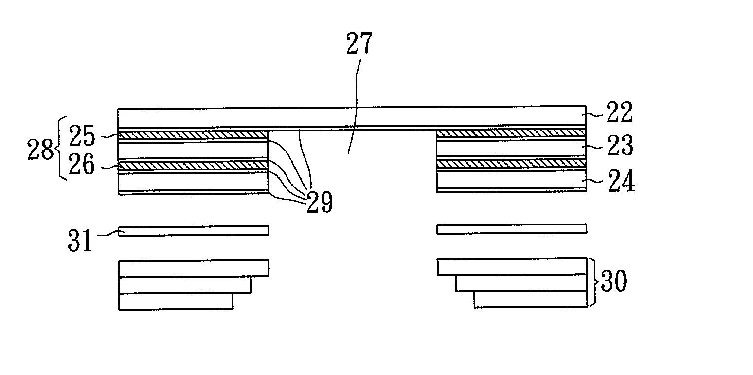
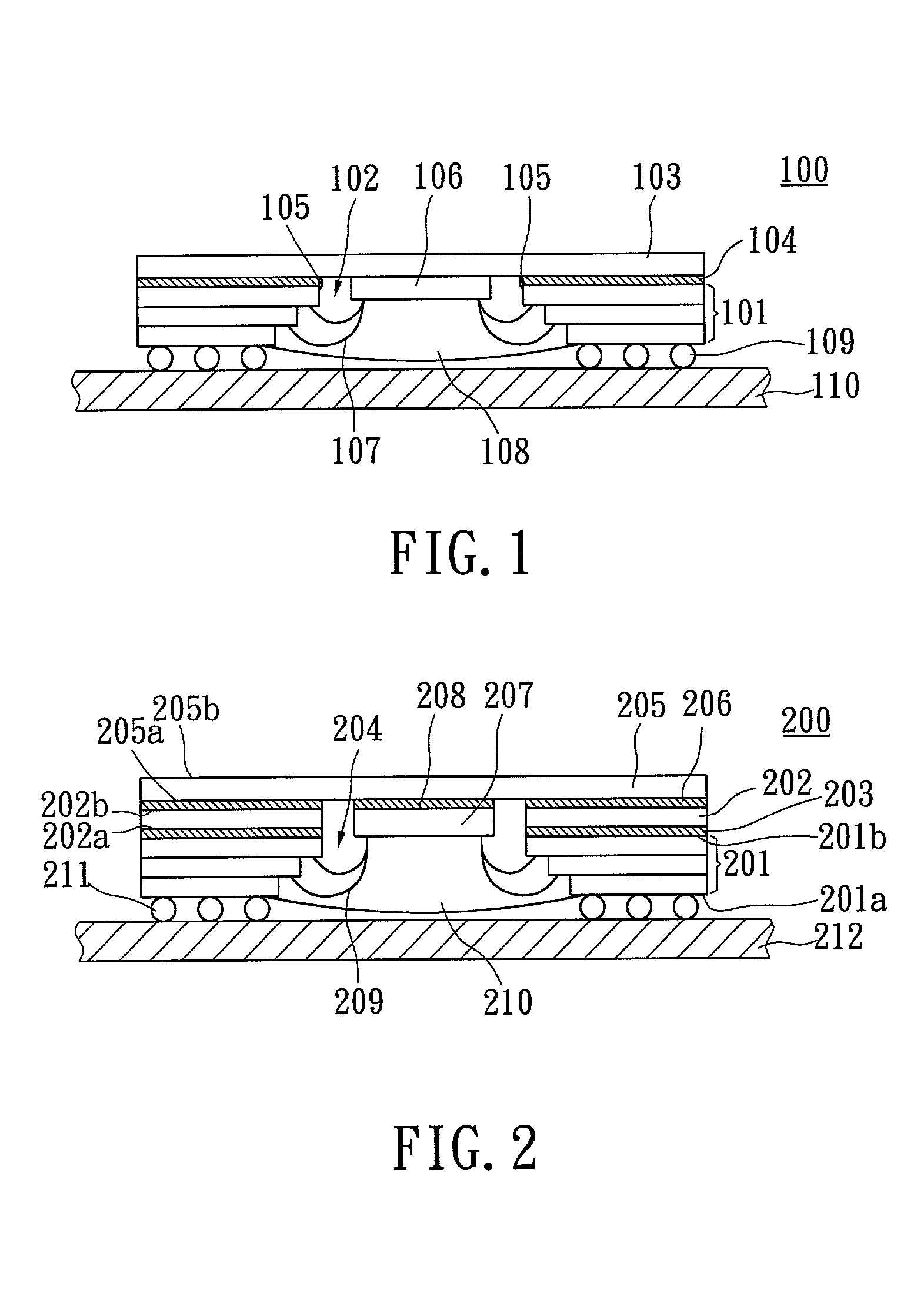
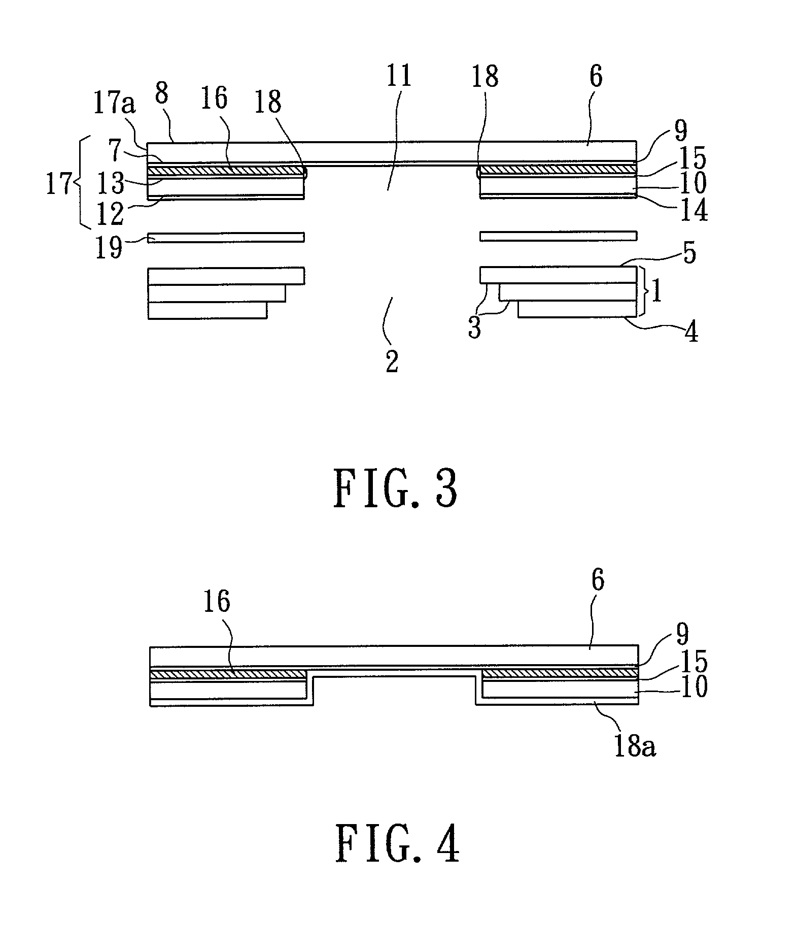
[0012] It is therefore an objective of the present invention to provide a stiff heat spreader element for making a cavity down plastic chip carrier having benefits of excellent heat dissipation characteristic, low weight, small thickness and low warpage and twist.

Problems solved by technology

However, heat density problems often arise with increased miniaturization, since the amount of heat generated by the device increases as the number of transistors fabricated onto a single semiconductor device increases.
However, low temperature stability experienced with plastic packages still remains as a problem.
In this method, when the heat spreader is made of copper base material, e.g. copper or copper base alloy, which is well known a relatively soft material, the cure shrinkage of the adhesive film may cause warpage during heat pressing the heat spreader together with the circuit board containing the stiffener.
This method would encounter the same problem as described above for U.S. Pat. No. 6,034,427, i.e. warpage of the fabricated BGA is difficult to be eliminated.

Method used


Image

  • Attachment of a stiff heat spreader for fabricating a cavity down plastic chip carrier
  • Attachment of a stiff heat spreader for fabricating a cavity down plastic chip carrier
  • Attachment of a stiff heat spreader for fabricating a cavity down plastic chip carrier

Examples


Embodiment Construction

[0024] For a better understanding on the advantages and capabilities of the present invention, reference is made to the following disclosure, appended claims in connection with the accompanying drawings. This invention, however, is embodied in many different forms and should not be construed as limited to the embodiments set forth herein. Rather, these embodiments are provided so that this disclosure will be thorough and complete, and will fully convey the scope of the invention to those skilled in the art.

[0025] The invention provides a stiff heat spreader that is further able to function as a stiffener for making a cavity down plastic chip carrier being devoid of warpage and twist. At the same time the efficiency of heat dissipation can even be higher. The method will be detailed hereinafter. Like numbers refer to like elements throughout. However, the figures are simply illustrative of the process, and are not drawn to scale, i.e. they do not reflect the actual dimensions or feat...


PUM


Abstract

A stiff heat spreader element for making a cavity down plastic chip carrier having benefits of excellent heat dissipation property, low weight, small thickness, low warpage and low twist is disclosed. The stiff heat spreader element is formed by bonding a heat spreader and a thermally conductive sheet with using a first bonding sheet. The first bonding sheet is a prepreg or prepregs made of fiber-reinforced resin. A second bonding sheet is used to bond a circuit substrate and the stiff heat spreader element. The second bonding sheet is made of a single adhesive layer or a stack of adhesive layers. The adhesive layer is made of an adhesive material, or a flake-filled adhesive material, or short fiber-filled adhesive material, or a particle-filled adhesive material. The second bonding sheet is not a prepreg or prepregs. The circuit substrate has an opening to receive an electronic chip.

Description

[0001] 1. Field of the Invention[0002] This invention relates generally to fabrication of the electronic packages, including single-chip packages and multichip packages, and in particular, to fabrication of a plurality of cavity down chip packages having heat spreaders which also function as stiffeners attached thereto.[0003] 2. Description of the Prior Art[0004] With continuing advances in the semiconductor industry, electronic circuitry and electronic packaging are often designed to utilize as little space as is practicable. Circuit space often is a valuable asset, which needs to be conversed, and a miniaturization of electronic circuits often improves speed, reduces noise and leads to other performance advantages. Such a miniaturization is desirable in electronics employed in various applications, such as aircraft, automobiles, cellular phones, hand carry computers, hand carry camcorders, etc. However, heat density problems often arise with increased miniaturization, since the am...

Claims


Application Information

Patent Timeline
IPC IPC(8): H01L23/10H01L23/31H01L23/36H01L23/373
CPCH01L23/10H01L23/3128H01L2924/014H01L2924/01033H01L24/48H01L2924/30107H01L2924/15321H01L2924/1532H01L23/36H01L23/3733H01L24/49H01L2224/48091H01L2224/48227H01L2224/49109H01L2224/73265H01L2924/01006H01L2924/01013H01L2924/01014H01L2924/0102H01L2924/01022H01L2924/01028H01L2924/01029H01L2924/0104H01L2924/01047H01L2924/01056H01L2924/01074H01L2924/01078H01L2924/01079H01L2924/14H01L2924/15153H01L2924/1517H01L2924/15311H01L2924/00014H01L2924/00H01L2924/15787H01L2924/12042H01L2924/181H01L2224/45099H01L2224/05599H01L2924/00012
Inventor TUNG, I-CHUNGYU, JIUN-SHIANCHEN, KUO-BINHSU, SHIH-PING
Owner PHOENIX PRECISION TECH CORP
Learn More