Power and optical frequency monitoring system and transmission system of frequency-modulated optical signal

a transmission system and optical signal technology, applied in the field of monitoring systems, can solve the problems of complex configuration and embodiment, low reliability and resolution, and large influence on system performance, and achieve the effects of preventing performance degradation, easy operation and management, and easy and economical operation

Inactive Publication Date: 2002-10-24
KOREA ADVANCED INST OF SCI & TECH
View PDF3 Cites 103 Cited by
  • Summary
  • Abstract
  • Description
  • Claims
  • Application Information

AI Technical Summary

Benefits of technology

0014] A transmission system including the frequency modulation means, and a monitoring system for extracting a power / optical frequency of a frequency-modulated optical signal can be realized easily and economically. Furthermore, those system may prevent the performance degradation due to the cross gain modulation (XGM) phenomenon of an optical amplifier and the Stimulated Raman Scattering (SRS) phenomenon of a fiber optic, and the interference between an amplitude-modulated pilot tone and a transmitting data signal. Accordingly, an optical communication network using a wavelength division multiplexing method can be operated and managed effectively.

Problems solved by technology

However, the optical frequency of an optical signal can be changed due to aging and temperature variation in an optical communication network of a wavelength division multiplexing method, and the optical frequency variation of each channel due to the different transmission characteristics of optical elements can lead to the output power variation of each channel and the crosstalk between neighboring is channels so that those may affect the system performance largely.
However, the prior art is only useful in term of simple configuration and easy embodiment, it has some disadvantages such as low reliability and resolution.
However, the conventional methods mentioned above require a complex configuration and embodiment, and are uneconomical due to expensive components in comparison with the measurement precision required by a monitoring system.
However, the foregoing conventional method shows disadvantages as following: the monitoring performance is degraded due to the cross gain modulation (XGM) phenomenon of an optical amplifier and the Stimulated Raman Scattering (SRS) phenomenon of a fiber optic, and the efficiency of data signal is declined due to the interference between an amplitude-modulated pilot tone and a transmitting data signal.
Furthermore, those system may prevent the performance degradation due to the cross gain modulation (XGM) phenomenon of an optical amplifier and the Stimulated Raman Scattering (SRS) phenomenon of a fiber optic, and the interference between an amplitude-modulated pilot tone and a transmitting data signal.

Method used


Image

  • Power and optical frequency monitoring system and transmission system of frequency-modulated optical signal
  • Power and optical frequency monitoring system and transmission system of frequency-modulated optical signal
  • Power and optical frequency monitoring system and transmission system of frequency-modulated optical signal

Examples


Embodiment Construction

[0028] Hereinafter, referring to appended drawings, the structures and the operation procedures of the embodiments of the present invention are described in detail.

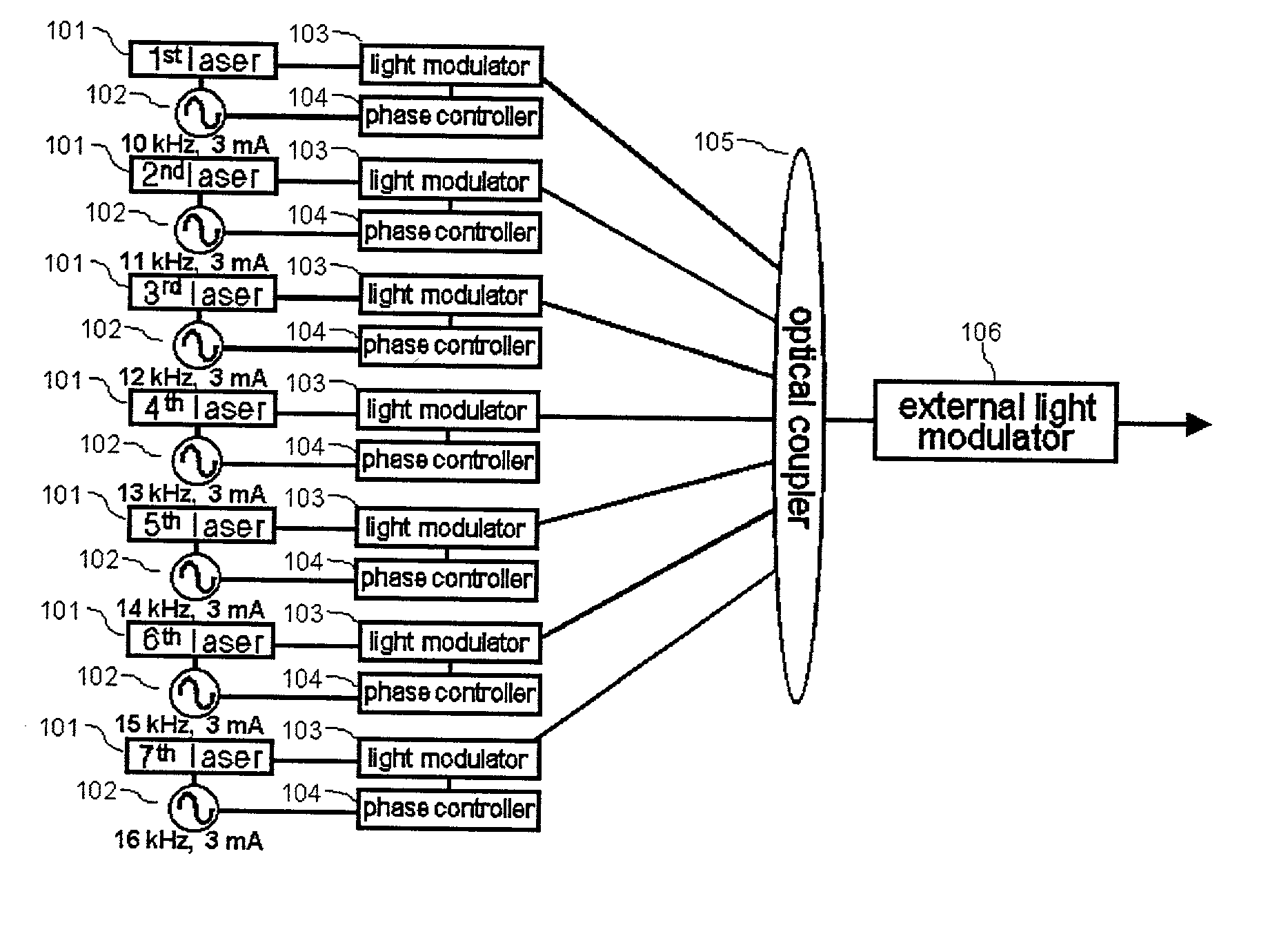
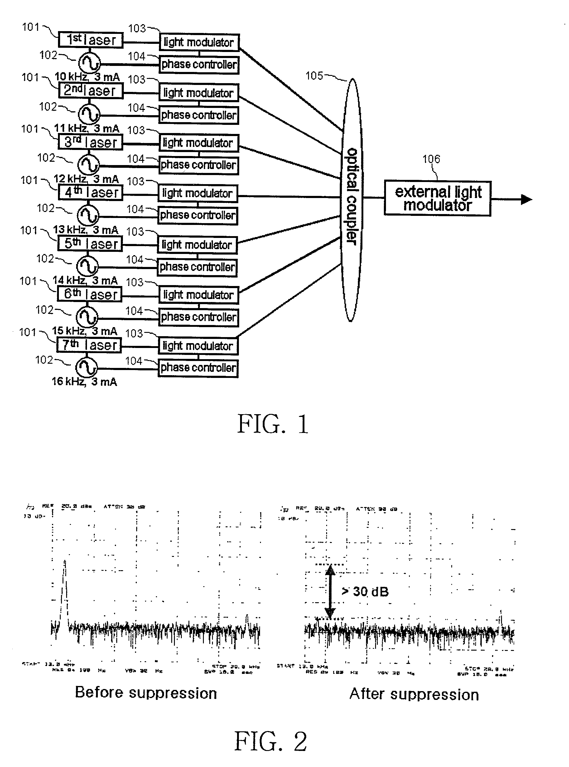
[0029] FIG. 1 is a configuration diagram depicting the preferred embodiment of a transmitter that is located at each node and generates a frequency-modulated optical signal in accordance with WDM optical communication network of the present invention. The transmitter for generating the frequency-modulated optical signal as shown in FIG. 1 comprises a Distributed FeedBack (DFB) laser (101) for generating an optical signal, a tone generator (102) for modulating the amplitude and frequency of an optical signal simultaneously by applying a tone signal to an optical signal, a phase controller (104) for controlling the phase of a tone signal, a light modulator (103) controlled by a phase controller for suppressing the amplitude variation of an optical signal of which amplitude is modulated by a tone generator, an optical couple...


PUM


Abstract

The present invention relates to a monitoring system that observes the power and optical frequency of a frequency-modulated optical signal, which is utilized in the communication network employing the WDM (wavelength division multiplexing) method. The monitoring system comprises demultiplex means for demultiplexing the frequency-modulated optical signal outputted from a transmitter including frequency-modulation means, photo-detection means for converting the output of demultiplex means into an electrical signal, and extraction means for extracting the power and optical frequency of an optical signal by measuring the magnitude of an amplitude-modulated tone.

Description

[0001] 1. Field of the Invention[0002] The present invention relates to a monitoring system that monitors the power and optical frequency of an optical signal, which is utilized in an optical communication network using the wavelength division multiplexing method. In more detail, it relates to a monitoring device that observes the power and optical frequency of an optical signal using demultiplexer and photo-detectors at monitoring nodes, after modulating the frequency of an optical signal outputted from a transmitter, in order to operate effectively an optical communication network of the wavelength division multiplexing method.[0003] 2. Description of the Related Art[0004] An optical communication network using the wavelength division multiplexing (WDM) method sets the multiplexed communication cannels according to the wavelength, and transmits multiple optical signals through the multiplexed communication cannels with high speed so that it can effectively make a communication net...

Claims


Application Information

Patent Timeline
Patent Type & Authority Applications(United States)
IPC IPC(8): H04B10/077H04J14/02
CPCH04B10/0775H04B2210/075H04J14/0221H04B10/2581
Inventor CHUNG, YEUN CHOLPARK, KEUN JUYUN, CHUN JU
Owner KOREA ADVANCED INST OF SCI & TECH
Why Eureka
Try Eureka