Step index optical fiber with doped cladding and core, a preform, and a method of fabricating such a fiber

a technology doped cladding, which is applied in the field of step index optical fiber with doped cladding and core, a preform, and a method of fabricating such a fiber, which can solve the problems of both of those solutions and suffer from drawbacks

Inactive Publication Date: 2002-11-14
ALCATEL LUCENT SAS
View PDF8 Cites 18 Cited by
  • Summary
  • Abstract
  • Description
  • Claims
  • Application Information

AI Technical Summary

Benefits of technology

0045] It is also advantageous for the power propagating in the portion of th...

Problems solved by technology

Both of those soluti...

Method used


Image

  • Step index optical fiber with doped cladding and core, a preform, and a method of fabricating such a fiber
  • Step index optical fiber with doped cladding and core, a preform, and a method of fabricating such a fiber

Examples


Embodiment Construction

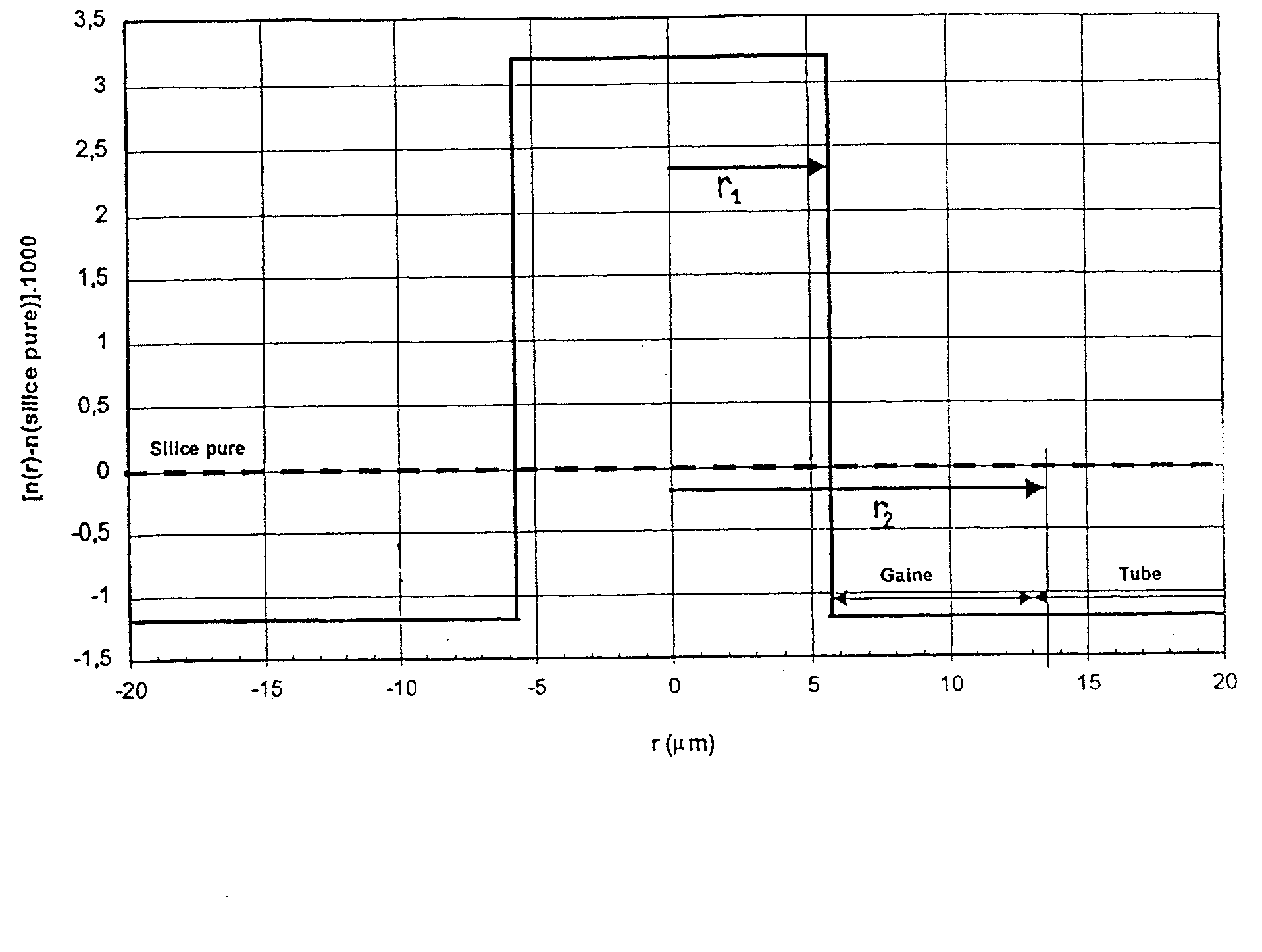
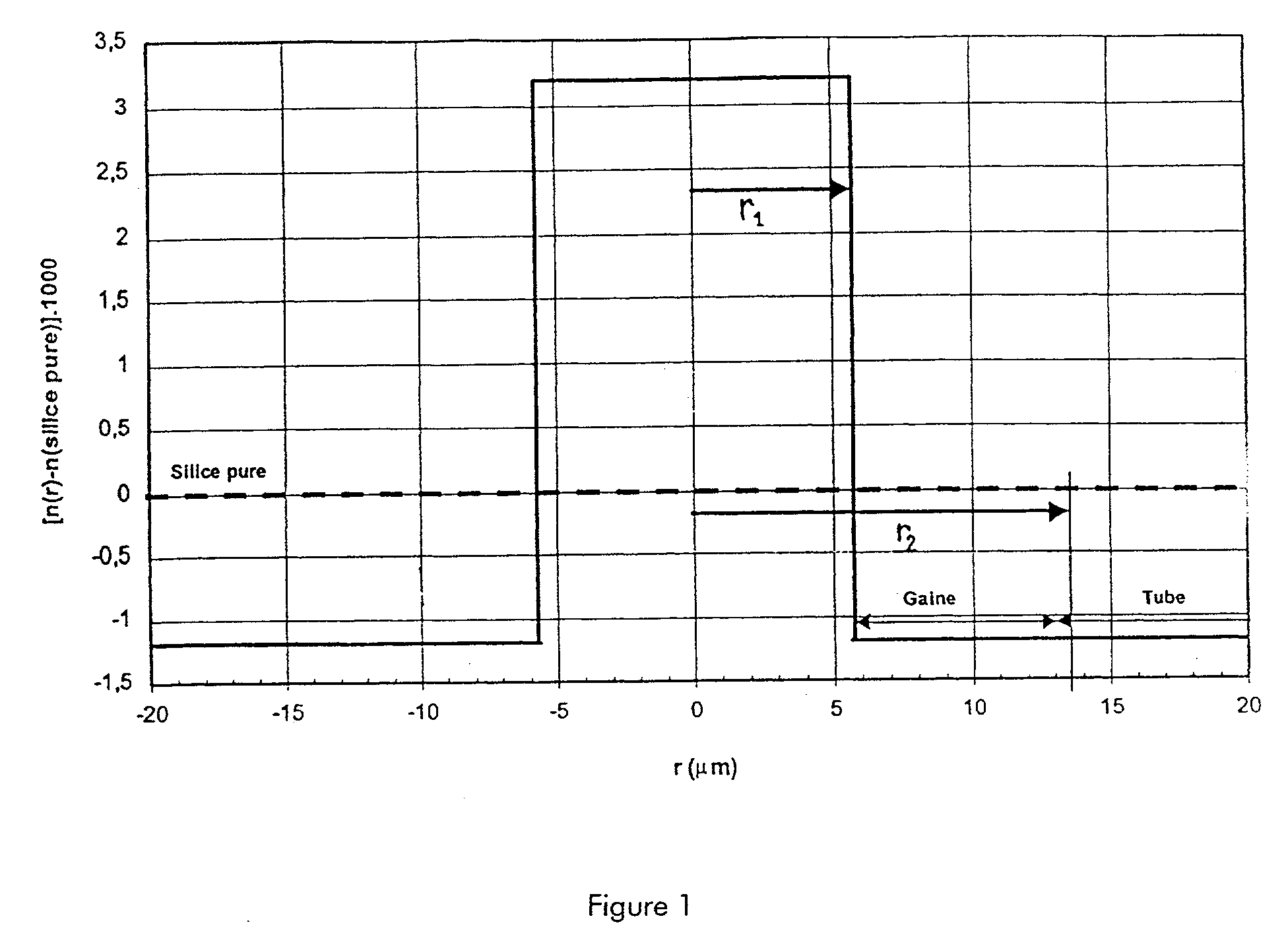
[0047] In order to fabricate a step index optical fiber by MCVD, the invention proposes using a deposition tube with an index-lowering dopant; doped inner cladding is deposited inside the tube, which cladding presents substantially the same refractive index as the deposition tube; and then a doped core is deposited presenting a refractive index that is higher than the index of the cladding and of the deposition tube. After collapsing, it is also advantageous to provide build-out material which is also doped to lower its index down to a value close to the index of the deposition tube.

[0048] The fiber obtained after drawing such a preform made using this method presents a core, inner cladding which corresponds to the doped inner cladding as deposited inside the deposition tube, and cladding which corresponds to the deposition tube; in the fiber obtained in this way, it is possible to distinguish between the cladding, the inner cladding, and the core of the fiber. The cladding comes fr...


PUM

PropertyMeasurementUnit
Fractionaaaaaaaaaa
Fractionaaaaaaaaaa
Fractionaaaaaaaaaa

Abstract

The invention provides a step index optical fiber which presents cladding having an index lower than the index of silica and a core with an index higher than the index of silica. The fiber is obtained by drawing a preform made by chemical vapor deposition using a deposition tube of index lower than the index of silica. Inner cladding of index substantially equal to the index of the deposition tube, and then a core of index higher than the index of the inner cladding are deposited in succession therein. The invention makes it possible to obtain a fiber having a large effective area, reduced attenuation, and suitable for being fabricated at low cost by chemical vapor deposition.

Description

[0001] The present invention relates to the field of optical fiber transmission, and more specifically to step index optical fibers used as line fibers in such transmission systems.[0002] The index profile of an optical fiber is generally described in terms of the appearance of the graph plotting the refractive index of the fiber as a function of radius. In conventional manner, the distance r to the center of the fiber is plotted along the abscissa axis and the difference between the refractive index and the refractive index of the fiber cladding is plotted up the ordinate axis. The index profile can thus be said to be "stepped", "trapezium-shaped", or "triangular" for graphs that are respectively step-, trapezium-, or triangle-shaped. Such curves are generally idealized profiles or reference profiles for the fiber, and fiber fabrication constraints can lead to a profile that departs perceptibly therefrom.[0003] It is conventional for the line fiber in optical fiber transmission sys...

Claims


Application Information

Patent Timeline
IPC IPC(8): C03B37/012C03B37/018G02B6/02G02B6/036
CPCC03B37/01205C03B37/01892C03B2201/12G02B6/02G02B6/03694G02B6/02242G02B6/02266G02B6/023G02B6/03688G02B6/02019
Inventor FLEURY, LUDOVICDE MONTMORILLON, LOUIS-ANNEBEAUMONT, FLORENTSILLARD, PIERREGORLIER, MAXIMENOUCHI, PASCALECAMPION, JEAN-FLORENTLABATUT, CHRISTINE
Owner ALCATEL LUCENT SAS
Why Eureka
Try Eureka