Friction material

a technology of friction material and friction material, which is applied in the direction of friction lining, shaft and bearing, mechanical apparatus, etc., can solve the problems of braking vibration and a reduction in the coefficient of friction, grinding the surface of the rotor, and abnormal wear of the rotor but also of the friction material itsel

Inactive Publication Date: 2002-11-14
ADVICS CO LTD
View PDF0 Cites 25 Cited by
  • Summary
  • Abstract
  • Description
  • Claims
  • Application Information

AI Technical Summary

Benefits of technology

[0019] The inorganic fiber to be used plays the role of suppressing the growth of the coating formed on the rotor. Therefore, the inorganic fiber should not be softened by the frictional heat. It is desirable that the inorganic fiber have a softening point of 850.degree. C. or higher.
[0022] It is desirable that the foregoing metal powder have a particle diameter of 1 to 180 .mu.m, more desirably 20 to 45 .mu.m. If less than 1 .mu.m, the material-manufacturing process becomes complicated and high-cost. If more than 180 .mu.m, the metal powder may cause an undesirable phenomenon similar to that which occurs when a metal fiber is added as described below.
[0023] The particle diameter of 20 .mu.m or more can secure the heat-dissipating quality of the friction material. The particle diameter of 45 .mu.m or less can suppress the mating-surface attacking. Furthermore, the particle diameter of 20 to 45 .mu.m is superior in mixing workability and material cost.
[0035] As described above, conventional friction materials are required to improve their performance when they are intended for use in brakes incorporating disk rotors or drums composed of an aluminum alloy. The present invention offers solutions to meet this requirement. Specifically, scoring that occurs when a composition including a metal fiber is used can be prevented by using the metal powder and inorganic fiber of the present invention in place of the metal fiber. The reduction in the coefficient of friction after a thermal histeresis can be suppressed by the addition of the inorganic fiber of the present invention. If the metal powder has an excessively large particle diameter, it loses its effect. Consequently, it is preferable to use a metal powder having a particle diameter of 1 to 180 .mu.m, more preferably 20 to 45 .mu.m. If the inorganic fiber is excessively hard, it attacks the mating material such as a rotor to a large extent. Therefore, it is preferable to use an inorganic fiber having a Mohs hardness of 3 to 5. Such a selection of material makes it possible to offer a friction material suitable for mating with a disk rotor or drum made of an aluminum alloy.

Problems solved by technology

Because the method (b) is complicated in manufacturing process and therefore costly, the method (a) has been adopted mainly in recent years.
The scoring causes not only abnormal wear of the rotor but also of the friction material itself, entailing the generation of braking vibration and a reduction in the coefficient of friction.
If the inorganic fiber is excessively hard, it grinds the surface of the rotor.
If excessively soft, it cannot remove the coating on the surface of the rotor.
If less than 1 .mu.m, the material-manufacturing process becomes complicated and high-cost.
If more than 180 .mu.m, the metal powder may cause an undesirable phenomenon similar to that which occurs when a metal fiber is added as described below.
If the metal powder is excessively hard, it may attack the mating material.
If the metal powder has an excessively large particle diameter, it loses its effect.
If the inorganic fiber is excessively hard, it attacks the mating material such as a rotor to a large extent.
However, repetition of hard rubbing increases the thickness of the coating on the surface of the rotor.
The metal fiber, however, has the above-described drawback.
However, if the inorganic fiber is excessively hard, it may attack the rotor at the same time that it removes the coating.

Method used

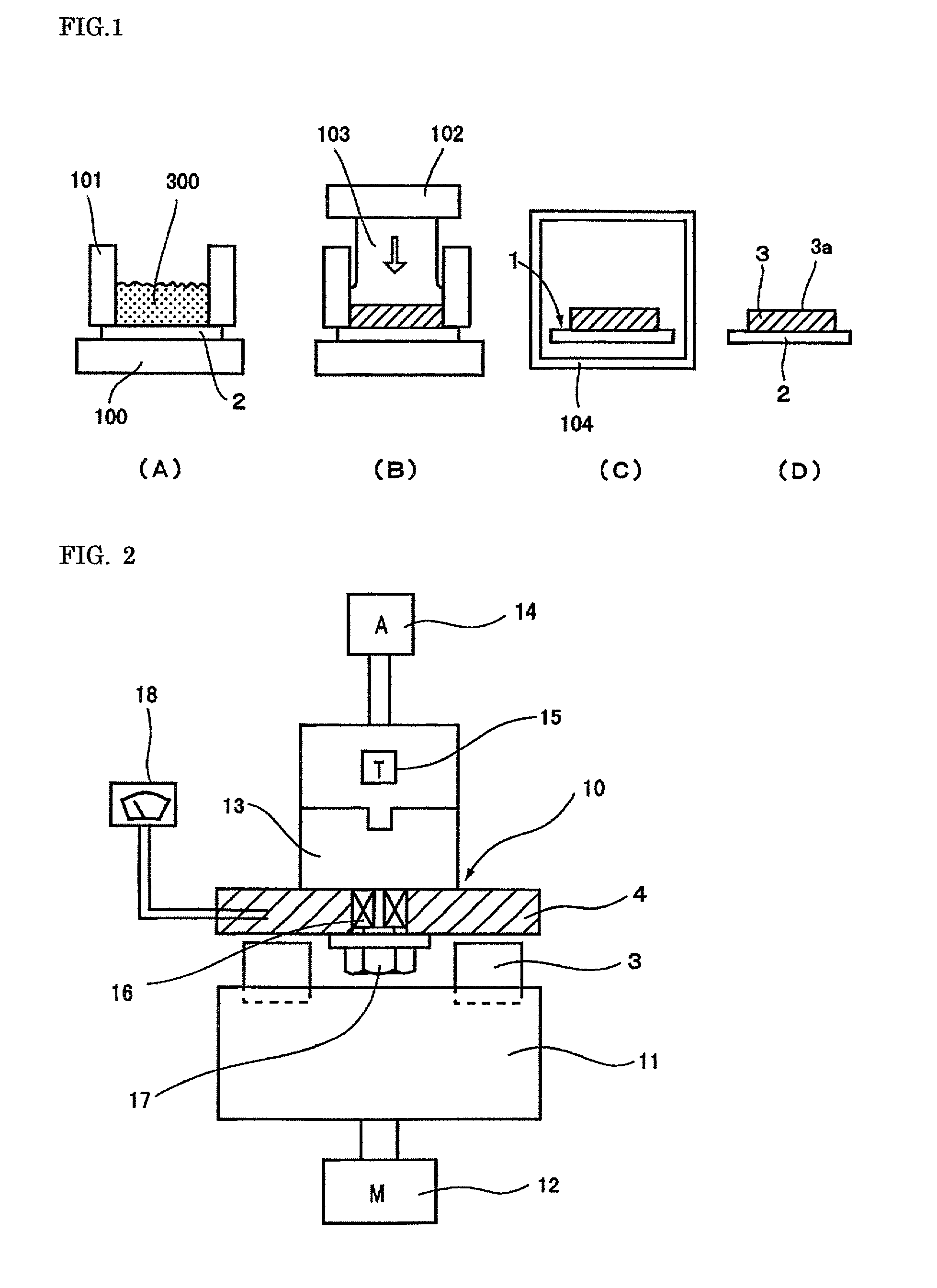
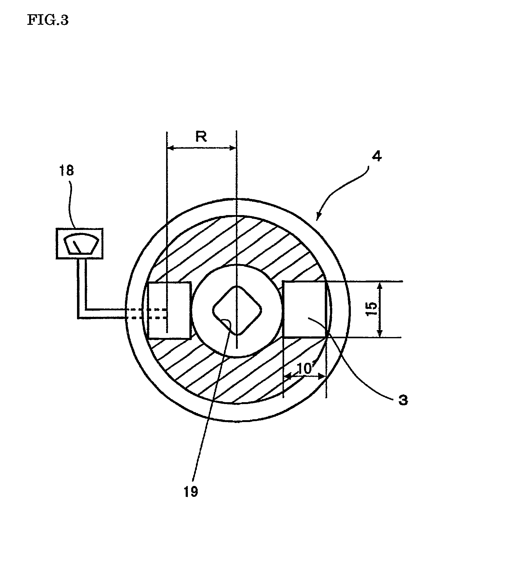

Image

  • Friction material
  • Friction material

Examples


Embodiment Construction

, which used an aluminosilicate fiber (CFF) having a Mohs hardness of 6, had a tendency to increase the wear of the rotor and friction material, despite a reduced added amount, in comparison with other examples that used a potassium titanate fiber having a Mohs hardness of 4 singly or in combination with slag wool having a Mohs hardness of 3.5.

[0070] An experiment was conducted to determine an optimum amount of the added inorganic fiber and metal powder. Table 3 shows the composition of the friction materials used. A metal powder having a particle diameter of 20 to 45 .mu.m was used because this range of particle diameter exhibited good results in comparison with other ranges of particle diameter shown in Table 1. Constituents other than the inorganic fiber and metal powder were used with different ratios from those shown in Table 1. The total amounts of the other constituents were maintained constant in vol % throughout the examples. The manufacturing method was the same as in the ...


PUM

PropertyMeasurementUnit
particle diameteraaaaaaaaaa
softening pointaaaaaaaaaa
particle diameteraaaaaaaaaa

Abstract

A friction material suitable for mating with a disk rotor or drum consisting mainly of an aluminum alloy reinforced by a hard material. The friction material suppresses the generation of a scoring on the disk rotor or drum. It also suppresses the change in the coefficient of friction before and after a heat history. The friction material comprises not only an organic-fiber base material, a binder resin, a friction-adjusting agent, a filler, and an inorganic powder, but also an inorganic fiber and a metal powder having a particle diameter of 1 to 180 mum.

Description

BACKGROUND OF TIE INVENTION[0001] 1. Field of the Invention[0002] The present invention relates to a friction material for brakes, clutches, etc. used in railroad cars, trucks, passenger cars, etc., especially a friction material that engages with a rotor or drum comprising an aluminum alloy reinforced by a hard material.[0003] 2. Related Background Arts[0004] FC 20 to 30 cast iron traditionally has been mainly used as a material for rotors and drums used in brakes, clutches, etc. However, in passenger cars, for example, an aluminum alloy reinforced by a hard material has increasingly been used to reduce the weight of the members to reduce fuel consumption.[0005] Not only are rotors and drums required to be light weight but also to have high resistance to heat and wear. To meet these requirements, they are produced, for example, by the following two methods:[0006] (a) a casting method in which a molten aluminum alloy is mixed with a hard material composed of a ceramic, such as silic...

Claims


Application Information

Patent Timeline
Patent Type & Authority Applications(United States)
IPC IPC(8): C08J5/14C22C49/14F16D69/02
CPCF16D69/026C22C49/14
Inventor OKAYAMA, KATSUYAYAMASHITA, YUKINORIFUJIKAWA, HIROYUKI
Owner ADVICS CO LTD
Why Eureka
Try Eureka