Differential fiber optical sensor with interference energy analyzer

a technology of energy analyzer and fiber optical sensor, which is applied in the direction of optical elements, force measurement by measuring optical property variation, instruments, etc., can solve the problems of difficult multiplexing into a single fiber line, unreasonable wavelength separation, etc., and achieve the effect of reducing temperature sensitivity

Inactive Publication Date: 2002-11-28
NAGANO KEIKI
View PDF7 Cites 45 Cited by
  • Summary
  • Abstract
  • Description
  • Claims
  • Application Information

AI Technical Summary

Benefits of technology

0006] Another object of the invention is to allow transver

Problems solved by technology

The major difficulty with this approach is that to obtain reasonable accuracy the wavelengths must be widely separated.
Fiber etalon based strain sensors based on a

Method used


Image

  • Differential fiber optical sensor with interference energy analyzer
  • Differential fiber optical sensor with interference energy analyzer
  • Differential fiber optical sensor with interference energy analyzer

Examples


Embodiment Construction

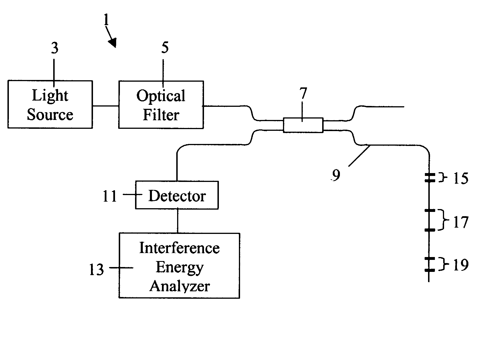
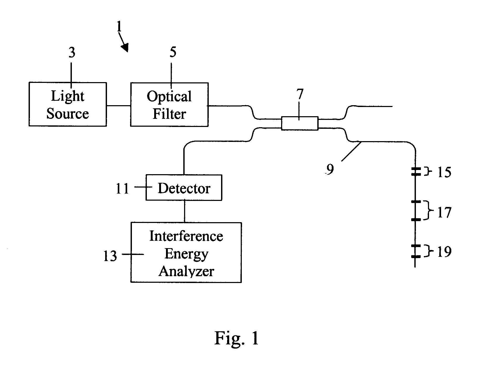
[0024] Referring to FIG. 1, the present invention comprises a differential fiber optic sensor system 1. This system includes a broadband light source 3 that directs a broadband spectral profile through both an optical filter 5 and an optical coupler 7, and into a test fiber 9 that contains a number of double-Bragg grating elements 15, 17, and 19. The light source 3 is operable to generate a broadband light radiation with the spectral width that exceeds or equals to a measurement wavelength range. The optical filter 5 could be a commercially available fiber Fabry-Perot tunable filter with an electrically controlled air gap. The transmission of the optical filter is characterized by a central transmission wavelength .lambda., which changes inside a particular wavelength range, and the transmission spectral width .DELTA..lambda.. The transmission spectral width satisfy following expression: 1 <2 l max g, ( 1 )

[0025] where l.sup.g.sub.max is maximum distance between two gratings in a do...


PUM


Abstract

A fiber optic sensor, which includes an interference energy analyzer, is used to measure strain and temperature distribution along a test fiber. The sensor includes the following: a plurality of double-Bragg grating elements positioned along a test fiber, a broadband light source which produces a broadband spectral profile that propagates along the test fiber, an optical filter that is able to change the parameters of the broadband spectral profile, an optical reflection detector, a fiber optic beamsplitter, and an interference energy analyzer. Each double-Bragg grating element consists of two weak Bragg gratings, separated by a distance unique to each element. The interference energy analyzer calculates the energies of the interference patterns, which are created by beams reflected from double-Bragg grating elements. The energy of the interference signal changes when the gratings in one element non-uniformly change its parameters due to non-equal temperature or strain influence on two gratings.

Description

[0001] This application claims the benefit of U.S. Provisional Application No. 60 / 290450 by Vasilii V. Spirin, Mikhail C. Shlyagin and Eric Udd, entitled "Differential Fiber Sensor with Interference Energy Analizer" which was filed on May 11, 2001.[0002] This invention relates to fiber optical sensors and, more particularly, to fiber Bragg grating sensors used to measure temperature and strain changes. An area that has been investigated closely is the measurement of longitudinal strain and temperature. M. Xu, H. Gieger and J. P. Dakin in "Multiplexed Point and Stepwise Continuous Fiber Grating Based Sensors: Practical Sensor for Structural Monitoring?", Proceedings of SPIE, Vol. 2294, p. 94, 1994 described the usage of dual overlaid fiber gratings to measure strain and temperature. The major difficulty with this approach is that to obtain reasonable accuracy the wavelengths must be widely separated. Fiber etalon based strain sensors based on air cavities that are sold commercially b...

Claims


Application Information

Patent Timeline
IPC IPC(8): G01D5/353G01L1/24G02B6/34
CPCG01D5/35303G01L1/246G02B6/2932G02B6/022G02B6/0218G01D5/35354
Inventor SPIRIN, VASILII V.SHLYAGIN, MIKHAIL G.UDD, ERIC
Owner NAGANO KEIKI
Why Eureka
Try Eureka