
Cathode ray tube having multiple field emission cathodes

a cathode ray tube and cathode technology, applied in the field can solve the problems of increasing the brightness limit limiting the achievability of cathode ray tubes, and increasing by a factor of two or thr

Inactive Publication Date: 2002-12-05
ALTERA CORP +1
View PDF0 Cites 4 Cited by
  • Summary
  • Abstract
  • Description
  • Claims
  • Application Information

AI Technical Summary

Problems solved by technology

Another limitation on brightness of cathode ray tubes arises from the use of a shadow mask.
Still, even with a FE cathode, a brightness increase by a factor of two or three above an oxide cathode CRT is about the limit of achievability.
This limitation is primarily caused by excessive space charge and phosphor power-dissipation limitations.
The method uses complicated electronics and is limited to specific applications.

Method used


Image

  • Cathode ray tube having multiple field emission cathodes
  • Cathode ray tube having multiple field emission cathodes
  • Cathode ray tube having multiple field emission cathodes

Examples


Embodiment Construction

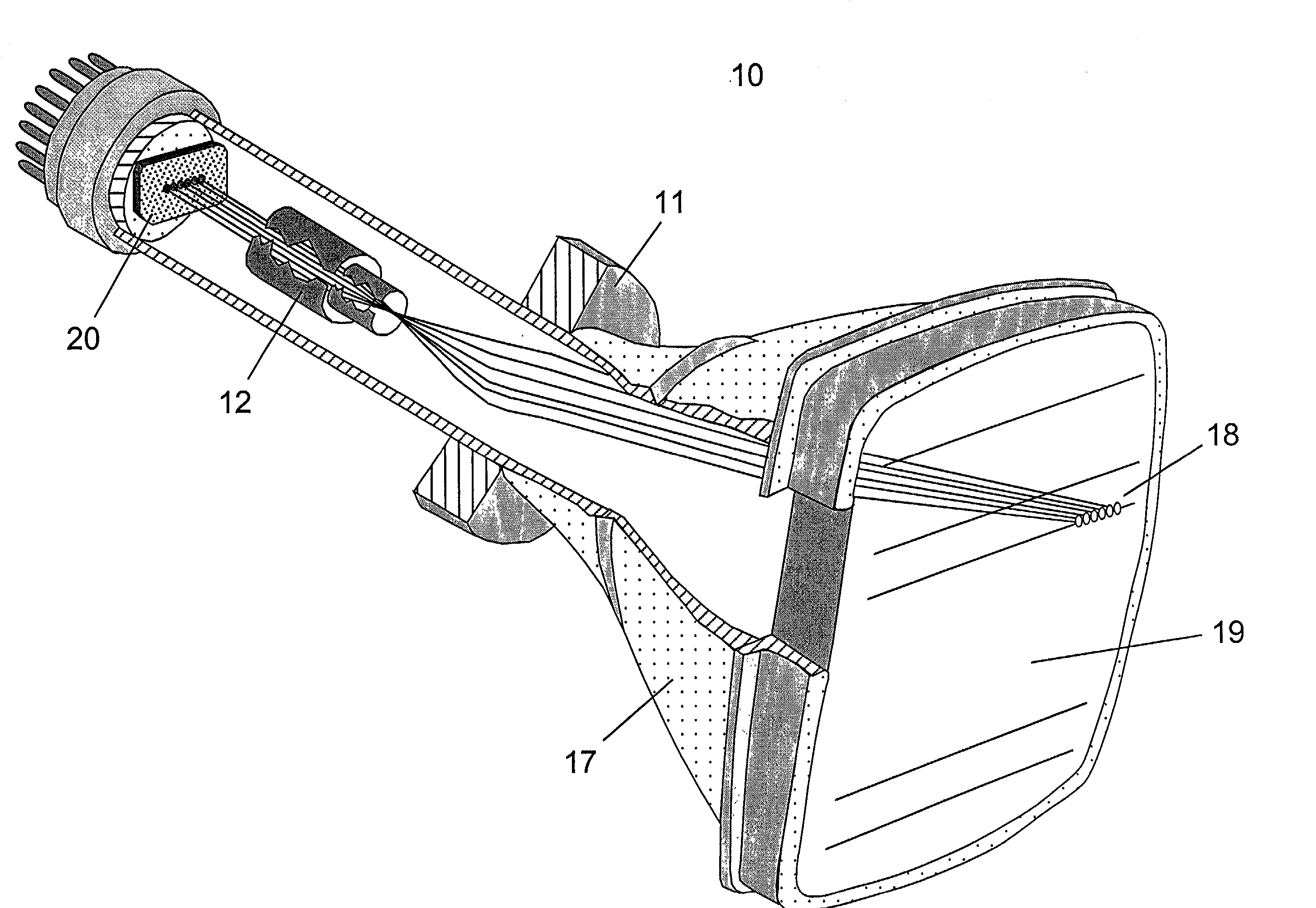
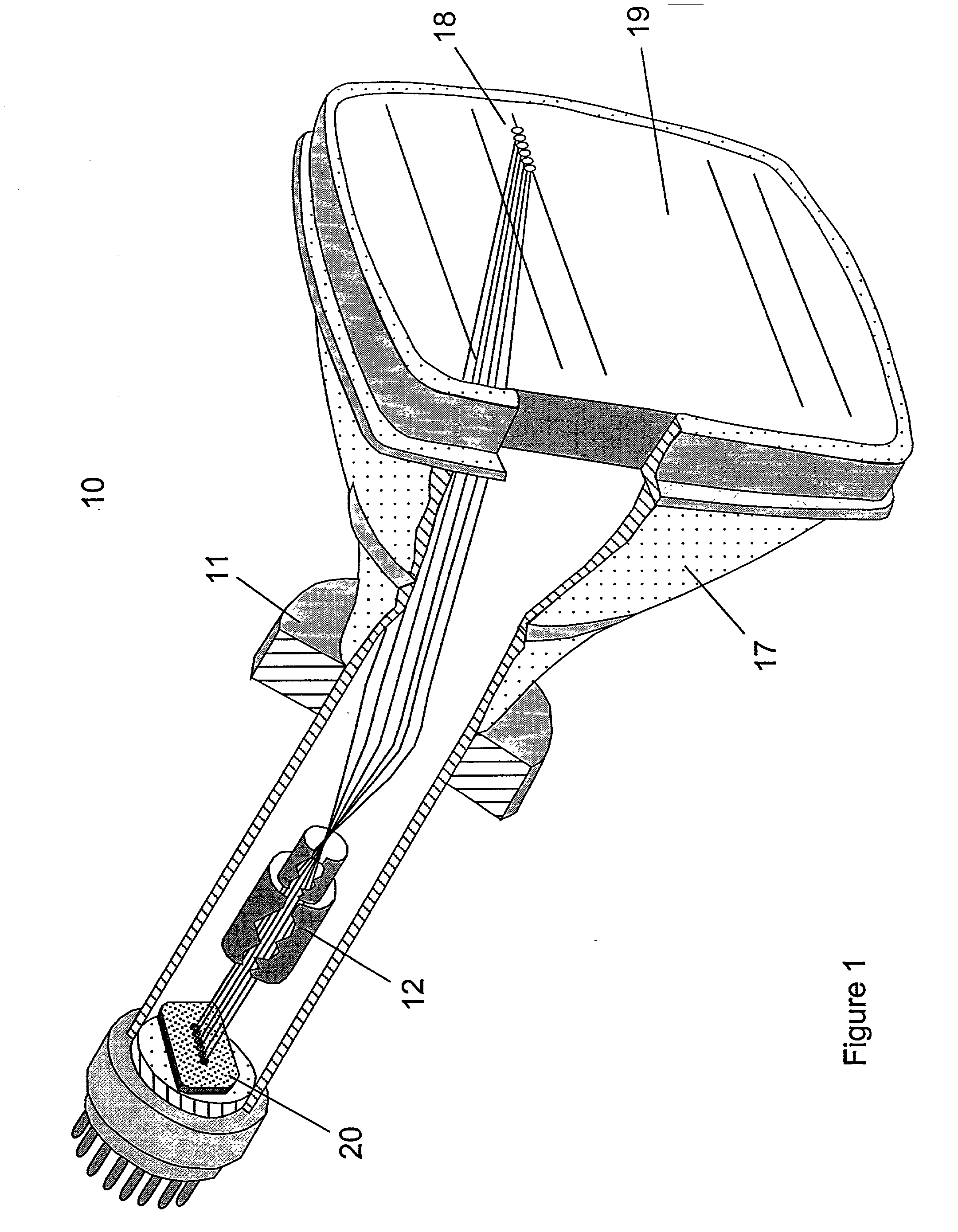
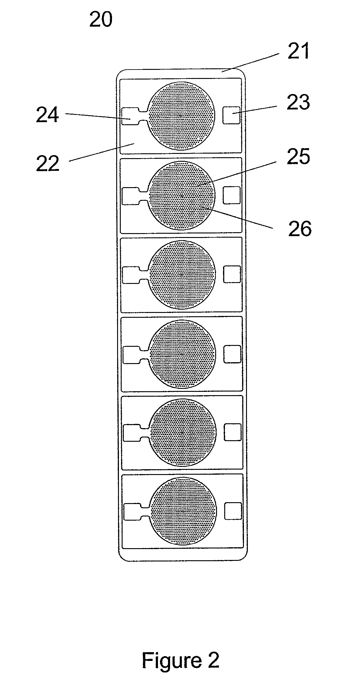
[0018] Referring to FIG. 1, the top view of a cathode ray tube having a field emission cathode is shown generally at 10. Multi-element field emission cathode 20 is at the source end of electron gun assembly 12. Gun assembly 12 is located inside the neck of envelope 17. Multi-element field emission cathode 20 will be described in more detail below. These electrodes comprising the gun assembly are operated at independent potentials such that electrons emitted from the plane of the cathode array are imaged on to phosphor screen 19. The electron gun elements combine to form the equivalent of a single optical lens that maps the electron field emission site at specific positions on the cathode array into an image of the array on the screen, modified only by the magnification of the electron optics and any aberration or other imperfections in the imaging. Methods for calculating such imaging of electron sources and electron beams are known, and are discussed, for example, in commonly assig...


PUM


Abstract

Apparatus and method are provided for using a multi-element field emission cathode in a color cathode ray tube. The field emission cathode may have from four to ten field emission arrays linearly arranged. The arrays are preferably formed from carbon-based material. An electron gun assembly focuses electron beams from each array on to a phosphor stripe or dot on the screen of the cathode ray tube. Deflection apparatus moves the beam from each field emission array according to clock signals. Clock signals also turn on or turn off voltage to contacts controlling electron current from the array. Values of voltage applied, determined by a video signal, determine the intensity of electron current from each array, which controls the intensity of the light emitted by each color stripe or dot of phosphor on the phosphor screen.

Description

[0001] 1. Field of the Invention[0002] This invention relates to cathode ray tubes. More particularly, the invention relates to an array of independently modulated electron beams emanating from field emission cathodes in a cathode ray tube.[0003] 2. Description of Related Art[0004] Higher brightness and simpler construction have long been the goal of manufacturers of cathode ray tubes ("CRTs"). In commercial CRTs, brightness is limited by the electron gun current that can be extracted from a thermionic cathode and passed through a small aperture. The small aperture is required to restrict the electron source size and produce a small spot of light on a phosphor screen.[0005] Another limitation on brightness of cathode ray tubes arises from the use of a shadow mask. The shadow mask is effectively a limiting aperture for the electron beam near the plane of the CRT screen. It normally captures from about 30 to 80 percent of the incident electron beam and reduces image brightness by a co...

Claims


Application Information

Patent Timeline
Patent Type & Authority Applications(United States)
IPC IPC(8): G09G1/00G09G1/04G09G3/10H01J1/14H01J1/304H01J19/06H01J23/34H01J29/00H01J29/48H01J29/50H01J29/74H01J29/98H01K1/04H04N5/14H04N9/20H04N9/24
CPCB82Y10/00H01J1/3042H04N9/20H01J2201/30469H01J29/503
Inventor ZOLLARS, BYRON G.LORR, JOHN J.KALAR, KENT R.
Owner ALTERA CORP
Learn More