Fuel injection system

a fuel injection system and fuel injection technology, applied in the direction of machines/engines, mechanical equipment, cylinders, etc., can solve the problems of shortening the service life of spark plugs, insufficient homogeneity, and additional impossibility of accurately dosing small quantities of fuel

Inactive Publication Date: 2002-12-12
ROBERT BOSCH GMBH
View PDF0 Cites 13 Cited by
  • Summary
  • Abstract
  • Description
  • Claims
  • Application Information

AI Technical Summary

Benefits of technology

[0009] The fuel injection system according to the present invention having the characterizing features of the main claim has the advantage over the related art due to the fact that with the provision of at least one row of injection orifices and a central injection orifice, a mixture cloud having a stoichiometric or slightly rich core (0.8<.lambda.<1.1) and a lean outer region (1.5<.lambda.<2.5) is formed in the combustion chamber.[0010] If the core of the mixture cloud is located in the area of the spark plug air gap at the moment of ignition, the core may ignite quickly, combust completely, and in turn ignite the lean outer region. This combustion method features particularly low nitrogen oxide emissions, since only a small portion of the mixture cloud, i.e., the interior stoichiometric core, burns at a high temperature so that only small quantities of nitrogen oxides are released, whereas the lean outer region, which occupies a significantly greater volume may combust at a lower temperature with negligible nitrogen oxide emissions.[0011] Advantageous refinements to the fuel injection system characterized in the main claim are possible through the measures characterized in the subclaims.[0012] The fact that the injection orifices in the at least one row of circumferentially arranged injection orifices and the central injection orifice have different diameters is particularly advantageous. By appropriate selection of the orifice diameter it is possible to create an injection cone having a more or less rich core.[0013] If the diameter of the central injection orifice is selected to be greater than that of the other injection orifices, it is also possible to lend a parachute-type shape to the conical injection jet, thus filling the combustion chamber better and also ensuring improved stoichiometric distribution in the mixture cloud.[0014] This may be realized particularly advantageously with two rows of circumferentially arranged injection orifices, if the diameters of the outer row of injection orifices are smallest, the injection orifices of the inner row are somewhat larger, and the central injection orifice has the largest diameter.[0015] A geometrical arrangement of the injection orifices of the inner and outer rows is also advantageous, according to which two injection orifices in the outer row correspond to one injection orifice in the inner row. The number of injection orifices per row is thus twice the number of injection orifices in the row immediately inferior thereto. In this way, not only the homogeneity but also the conformation and stoichiometry of the mixture cloud may be controlled.

Problems solved by technology

The methods of mixture formation and fuel injection systems described in the documents cited particularly share the disadvantages of inadequate homogeneity of the mixture cloud, and the problem of transporting the ignitable mixture to the region of the spark plug's air gap.
This results in heavy sooting of the spark plug and frequent thermal shocks, which shorten the service life of the spark plug.
The disadvantage of the method described in German Patent 196 42 653 C1 for the formation of an ignitable fuel-air mixture is the additional impossibility of accurately dosing small quantities of fuel, particularly in stratified charge operation, because the opening and closing times of the fuel injector cannot be controlled with sufficient precision.
It is furthermore disadvantageous that complicated combustion chamber geometries and fuel injectors with swirl arrangement are difficult and expensive to produce.

Method used


Image

  • Fuel injection system
  • Fuel injection system
  • Fuel injection system

Examples


first embodiment

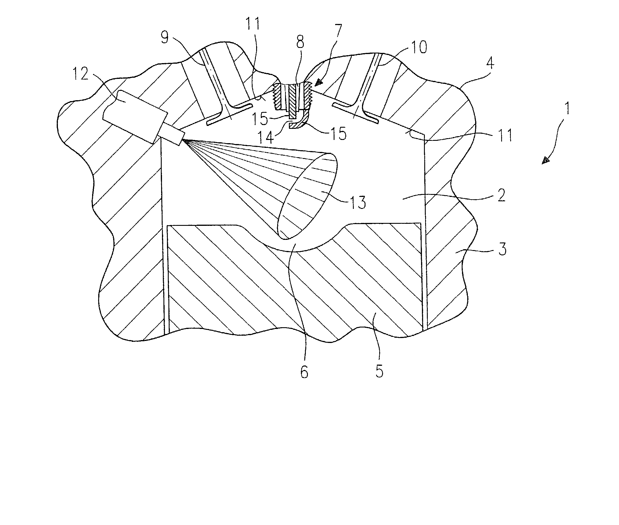
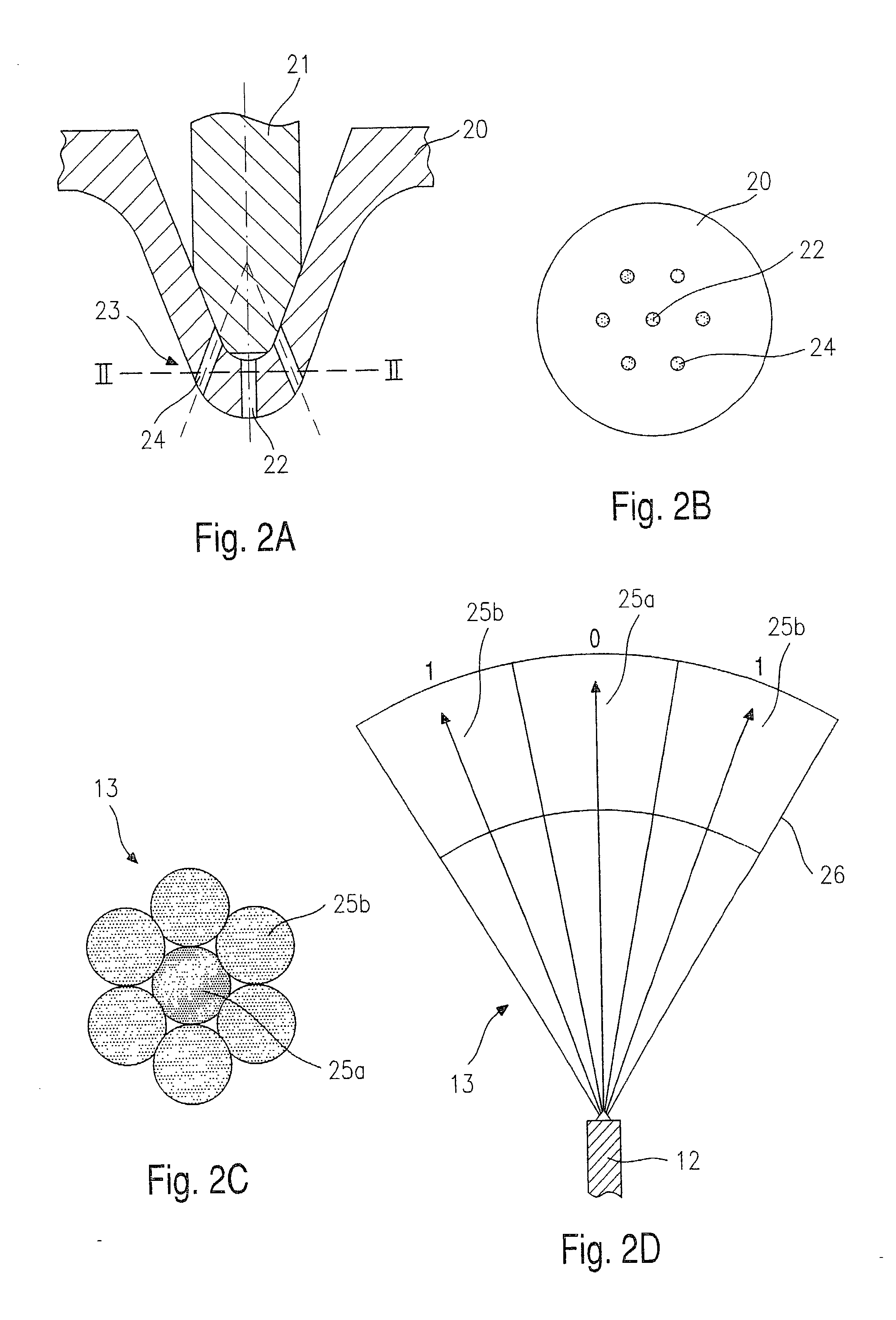
[0025] FIGS. 2A-2D show a longitudinal and a cross-sectional view through a valve body 20 of fuel injector 12 of a fuel injection system 1 according to the present invention, and a longitudinal and a cross-sectional view through mixture cloud 13 produced by fuel injector 12.

[0026] FIG. 2A is a schematic diagram of a longitudinal section of the injection side part of fuel injector 12 having a valve body 20 that operates in conjunction with a valve closing body 21. Valve body 20 is furnished with a central injection orifice 22 and a row 23 of circumferentially arranged injection orifices 24.

[0027] When fuel injector 12 is in the quiescent state, injection orifices 22 and 24 are closed off by valve closing body 21. If fuel injector 12 is actuated by a magnetic or piezoelectric actuator, valve closing body 21, which is connected to a valve needle (not shown) is lifted away from valve body 20 and frees the path to injection orifices 22 and 24. Fuel is injected through these into combusti...

second embodiment

[0031] Similarly to FIGS. 2A-2D, FIGS. 3A-3D show longitudinal and cross-sectional views of the jetting part of fuel injector 12, and a longitudinal and a cross-sectional view through mixture cloud 13 produced thereby.

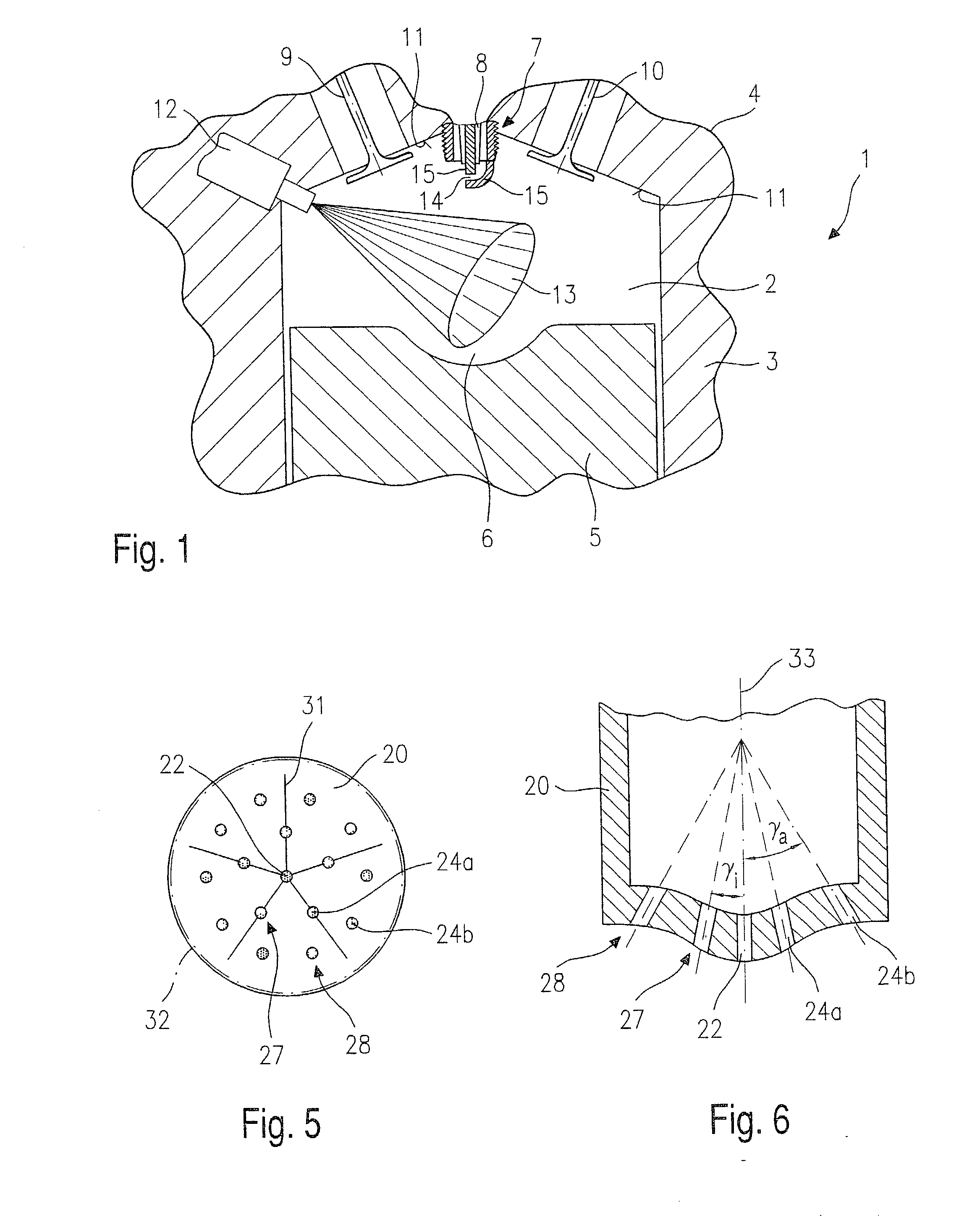
[0032] FIG. 3A again shows the injection side part of fuel injector 12 with the valve closing body 21 and valve body 20. In the present, second embodiment, valve body 20 is furnished with an inner row 27 of circumferentially arranged injection orifices 24a, and an outer row 28 of circumferentially arranged injection orifices 24b in addition to central injection orifice 22. When fuel injector 12 is actuated, valve closing body 21 is lifted away from valve body 20 and frees the path to injection orifices 22 and 24a and 24b.

[0033] FIG. 3B shows a sectional view through valve body 20 along the line III-III indicated in FIG. 3A. Injection orifices 24a of inner row 27 and injection orifices 24b of outer row 28 are arranged around central injection orifice 22. In this embodim...


PUM


Abstract

A fuel injection system for internal combustion engines comprises a fuel injector that injects fuel into a combustion chamber, the combustion chamber being delimited by a cylinder wall in which a piston is guided, and a spark plug that protrudes into combustion chamber. The fuel injector produces a conical mixture cloud in the combustion chamber through at least one row of injection orifices arranged circumferentially on a valve body of the fuel injector. The valve body also provides a centrally arranged injection orifice that produces a central area of the mixture cloud directed towards the spark plug.

Description

BACKGROUND INFORMATION[0001] The present invention is based on a fuel injection system according to the definition of the species of the main claim.[0002] German Patent Application 198 27 219 A1 describes a fuel injection system for an internal combustion engine having an injector with a fuel jet adjustment plate, which is furnished with first nozzle orifices that are arranged in a first circle, and second nozzle orifices that are arranged in a second circle. The second circle has a diameter that is greater than that of the first circle. The circles are arranged coaxially to a center line of the adjustment plate. Each orifice axis of the second nozzle orifices forms an acute angle with a reference plane, which is perpendicular to the center line of the valve body. The angle is smaller than the angle that is formed between the reference plane and each orifice axis of the first nozzle orifices. In that way, atomized fuel that is injected through first nozzle orifices may be directed a...

Claims


Application Information

Patent Timeline
Patent Type & Authority Applications(United States)
IPC IPC(8): F02B23/10F02B75/12F02F1/24F02M61/18
CPCF02B23/104F02B2023/103F02B2075/125Y02T10/123F02M61/182F02M61/1826Y02T10/125F02F2001/245Y02T10/12
Inventor ARNDT, STEFANHERDEN, WERNER
Owner ROBERT BOSCH GMBH
Why Eureka
Try Eureka