Projection optical system and exposure apparatus having the projection optical system

a technology of projection optical system and projection optical system, which is applied in the direction of photomechanical apparatus, instruments, printers, etc., can solve the problems of difficult to obtain the required homogeneity of optical material blocks, and difficult to manufacture optical systems of good performan

Inactive Publication Date: 2003-02-13
NIKON CORP
View PDF6 Cites 768 Cited by
  • Summary
  • Abstract
  • Description
  • Claims
  • Application Information

AI Technical Summary

Problems solved by technology

As a result, the outer diameter (the glass material diameter) of the block of optical material from which this lens is manufactured also becomes great, and it becomes difficult to obtain an optical material block of the required homogeneity, and therefore it is hard to manufacture an optical system of good performance.
Furthermore, when the lens outer diameter becomes great, the lens can easily be influenced by bending or distortion due to its weight, which also makes it difficult to manufacture an optical system of good performance.
As a result the structure of the optical system becomes complicated and the lens outer diameter becomes large, and it becomes difficult to implement an optical system of a realistic size.
On the other hand, when the working distance D drops below the lower limit value of the above condition (1), the working distance D becomes too small, and the operability and so on of the optical system is remarkable deteriorated.
In particular, in the case of an exposure apparatus, it becomes difficult to prevent gas generated due to irradiation from the resist which is coated upon the wafer (in the following this phenomenon is termed "out-gassing") from adhering to the surface of the lens which is closest to the image side.
Furthermore, along with it becoming difficult to perform autofocusing upon the wafer surface, the danger of contacting the wafer against the projection optical system when changing the wafer becomes very high.
When the upper limit value of the above condition (2) is exceeded, just as in the above case when the upper limit value of the condition (1) is exceeded, the working distance D becomes too large, and the incidence of high order spherical aberration becomes great, so that the structure of the optical system becomes complicated and the lens outer diameter becomes undesirable large.
On the other hand, when the lower limit value of the above condition (2) is dropped below, just as in the above case when the lower limit value of the above condition (1) is dropped below, the wo

Method used


Image

  • Projection optical system and exposure apparatus having the projection optical system
  • Projection optical system and exposure apparatus having the projection optical system
  • Projection optical system and exposure apparatus having the projection optical system

Examples


embodiment two

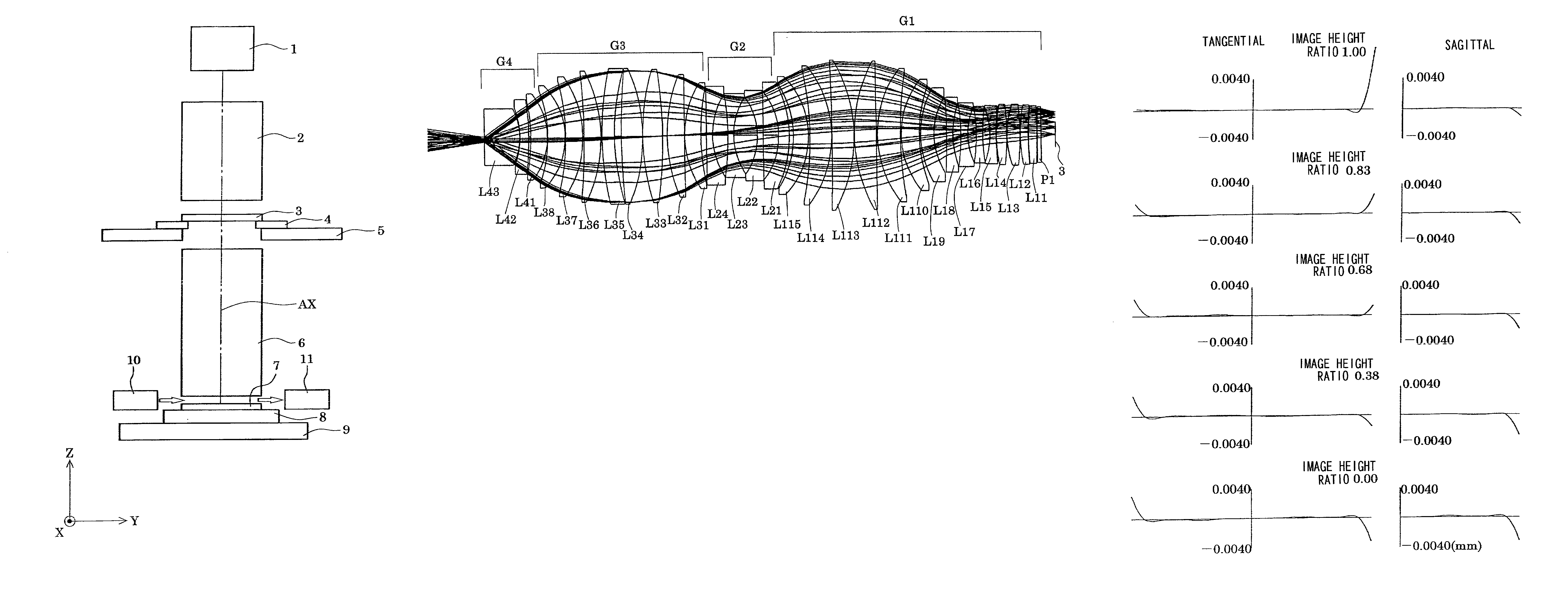
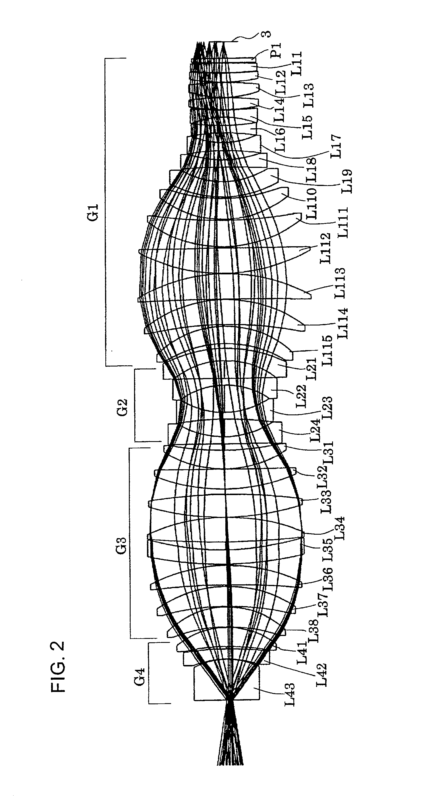
[0060] FIG. 4 is a figure showing the structure of lenses of a projection optical system according to the second preferred embodiment of the present invention. In the lenses of FIG. 4, a first lens group G1 comprises, in order from the mask side: a parallel plane plate P1; a biconvex lens L11; another biconvex lens L12; yet another biconvex lens L13; still yet another biconvex lens L14; a negative meniscus lens L15 which presents its convex surface to the mask side; a biconvex lens L16; another biconvex lens L17; yet another biconvex lens L18; a negative meniscus lens L19 which presents its concave surface to the mask side; a positive meniscus lens L110 which presents its concave surface to the mask side; another positive meniscus lens L111 which presents its concave surface to the mask side; a biconvex lens L112; another biconvex lens L113; a positive meniscus lens L114 which presents its convex surface to the mask side; and another positive meniscus lens L115 which presents its co...

embodiment three

[0066] FIG. 6 is a figure showing the structure of lenses of a projection optical system according to the third preferred embodiment of the present invention. In the lens of FIG. 6, a first lens group G1 comprises, in order from the mask side: a biconcave lens L11; a biconvex lens L12; another biconvex lens L13; a positive meniscus lens L14 which presents its convex surface to the mask side; a negative meniscus lens L15 which presents its convex surface to the mask side; a biconcave lens L16; another biconcave lens L17; a positive meniscus lens L18 which presents its concave surface to the mask side; a biconvex lens L19; another biconvex lens L20; a positive meniscus lens L21 which presents its convex surface to the mask side; and another positive meniscus lens L22 which presents its convex surface to the mask side.

[0067] Furthermore, a second lens group G2 comprises, in order from the mask side: a negative meniscus lens L23 which presents its convex surface to the mask side; anothe...


PUM


Abstract

A projection optical system according to the present invention whose image side numerical aperture is greater than or equal to 0.75, and which forms an image of a first object upon a second object using light of a predetermined wavelength less than or equal to 300 nm, comprises: a first lens group G1 of positive refractive power; a second lens group G2 of negative refractive power; a third lens group G3 of positive refractive power; and a fourth lens group G4 of positive refractive power, and: the first lens group G1, the second lens group G2, the third lens group G3 and the fourth lens group G4 are arranged in order from a side of the first object; and a distance D in mm along an optical axis between an optical surface of the fourth lens group G4 closest to the second object, and the second object, satisfies a condition of 0.1<D<5.

Description

INCORPORATION BY REFERENCE[0001] The disclosure of the following priority application is herein incorporated by reference:[0002] Japanese Patent Application No. 2000-375992 filed Dec. 11, 2000.[0003] 1. Field of the Invention[0004] The present invention relates to a projection optical system and to an exposure apparatus to which such a projection optical system is fitted, and more particularly relates to a projection optical system which is suitable for an exposure apparatus which is used for the manufacture of semiconductor elements or liquid crystal display elements and the like by a process of photolithography.[0005] 2. Description of the Related Art[0006] In a photolithography process for manufacture of semiconductor elements or the like, there is employed an exposure apparatus for projecting and exposing an image of a pattern upon a mask via a projection optical system onto a photosensitive substrate such as a wafer with this type of exposure apparatus, the resolving power whic...

Claims


Application Information

Patent Timeline
IPC IPC(8): G02B13/14G02B27/18G03F7/20
CPCG02B13/143G02B27/18G03F7/70241G03F7/70341
Inventor SUENAGA, YUTAKA
Owner NIKON CORP
Why Eureka
Try Eureka