Cryogenic medical device with high pressure resistance tip

a medical device and tip technology, applied in the field of medical devices, can solve the problems of significant degradation of the cooling power of the device, cryogen vapor, sublimation or precipitation, etc., and achieve the effect of reducing the pressure and high pressure resistance tip

Inactive Publication Date: 2003-03-27
MEDTRONIC CRYOCATH LP
View PDF0 Cites 15 Cited by
  • Summary
  • Abstract
  • Description
  • Claims
  • Application Information

AI Technical Summary

Benefits of technology

0014] The invention discloses a cryogenic medical device with high pressure resistance tip, and a method for cooling the same.
0015] In one embodiment of the invention, the medical device comprises a first member defining an injection lumen, a second member circumferentially disposed around the first member to define a return lumen therebetween. The return lumen has at least one cross-sectional area. A third member is disposed between the second member and the first member to define a restriction lumen between the third member and the first member. The restriction lumen has at least one cross-sectional area smaller than the at least one cross-sectional area of the return lumen. In another embodiment of the invention, the medical device comprises an elongate injection tube having a proximal end portion having at least one proximal orifice, and a distal end portion having at least one distal orifice, and an elongate catheter tube circumferentially disposed around the injection tube and defining a return lumen therebetween. The catheter tube has a distal end portion, the distal end portion being coupled to a thermally transmissive element, where the thermally transmissive element circumferentially encloses the distal end portion of the injection tube. A restriction tube is circumferentially disposed inside of the catheter tube and encloses a portion of the return lumen proximate the thermally transmissive element.
0016] Finally, a method for cooling the cryogenic medical device is disclosed. The method includes the steps of: (i) providing a supply of cryogen at a pressure of at least two atmospheres absolute pressure in a storage container; (ii) fluidly connecting said supply of cryogen with a catheter having a first lumen inside of a second lumen, and a thermally transmissive element; (iii) providing a flow regulation system to dispense cryogen into the first lumen and to reduce the pressure in the second lumen to below one atmosphere absolute pressure; (iv) controllably injecting said supply of cryogen through the first lumen in proximity to the thermally transmissive element; and (v) providing a third lumen inside of the second lumen, the third lumen being proximal to the thermally transmissive element, the third lumen having a cross-sectional area smaller than the cross-sectional area of the second lumen.

Problems solved by technology

This warming, coupled with head losses in the flow of cryogen down a length of several hundred diameters of tubing, acts to degrade the quality of cryogen from its high pressure liquid form to a lower pressure, higher temperature, mixed phase form, leading to significantly degraded cooling power of the device.
Another problem presented in such a cooling process is that the cryogen vapor which rapidly cools in the expansion chamber may, if the resultant pressure drop is extreme enough, sublimate or precipitate if the pressure drops below that of the triple point for the cryogen.
This sublimation naturally degrades the cooling power of the device, as heat transfer is drawn from the cryogen vapor into the cryogen particulate, rather than from the tissue proximate the device into the vapor.
Worse, sublimation leads to unsteady flow, non-uniform density, and unstable temperature and non-equilibrium conditions.
The sublimed particles may also block the flow of cryogen in the relatively small lumens, thereby creating dangerous high pressure conditions in the tip.
Furthermore, because the catheter based device is to be inserted into a body lumen or other internal region of the human body, the device must maintain a fluid seal, lest potentially damaging cryogen leak during application of the device.

Method used


Image

  • Cryogenic medical device with high pressure resistance tip
  • Cryogenic medical device with high pressure resistance tip

Examples


Embodiment Construction

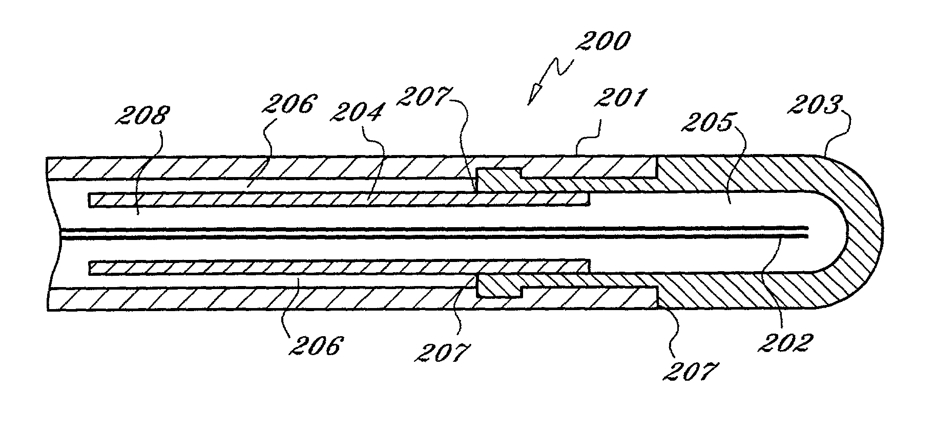
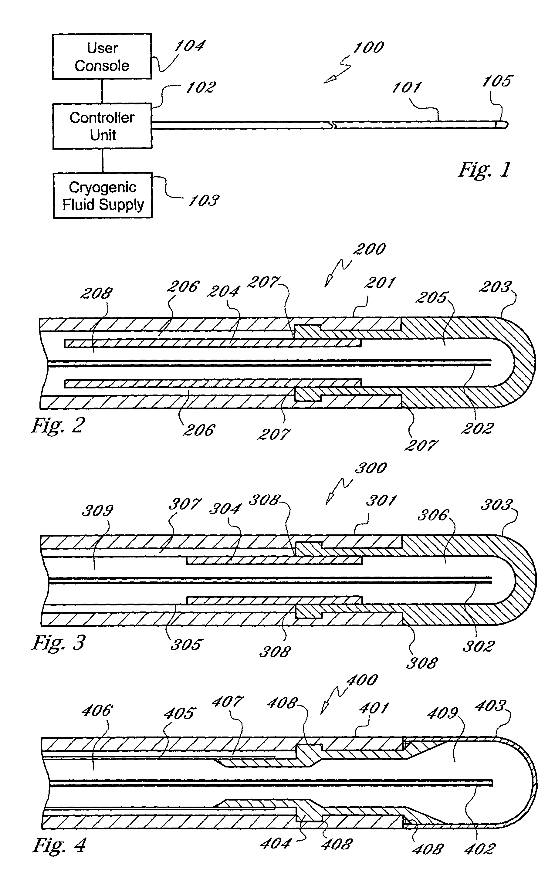
[0022] As used herein, the term "cryogen" or "cryogenic fluid" refers to a fluid substance with properties suitable for: (i) steady flow through ducts of small diameter, (ii) high pressure compression into liquid phase, and (iii) evaporation and expansion to gas phase at low temperatures, typically at saturation temperature or in the range of -10 to -130 degrees centigrade The cryogen may be any suitable, relatively inert "working fluid", such as nitrogen, nitrous oxide, or carbon dioxide, or refrigerants such as chlorodifluoromethane, ethyl alcohol, or Freon (a trademark of DuPont), or any number of other refrigerants or fluids with a high thermal energy transfer capacity and low boiling point, as are commonly known to those skilled in the art.

[0023] As used herein, the term "tube" refers to an elongate duct or conduit suitable for conveying a fluid. The tube may comprise any number of elements or members, and may have a varying range of properties and dimensions, such as length, t...


PUM


Abstract

The present invention provides a medical device to cold treat desired regions. An injection tube with an open distal end is disposed inside of a catheter tube, defining a return lumen therein. A supply of cryogenic fluid, regulated by a controller mechanism coupled to the device, flows through the injection tube and into the distal tip portion of the catheter tube, whereupon the fluid is returned from the catheter through the return lumen. The expansion and evaporation of cryogenic fluid inside the device serves to cool the surrounding areas external to and proximate the distal end of the device. An additional restriction tube is provided in the length of the catheter tube to regulate the pressure of the flow of cryogen therethrough so as to create higher operating pressures in the distal end of the device and thereby enhance the cooling power and temperature stability of the device at a lower range of fluid flow rates without reaching the triple point of the cryogenic fluid.

Description

CROSS-REFERENCE TO RELATED APPLICATION[0001] Not applicable.STATEMENT REGARDING FEDERALLY SPONSORED RESEARCH OR DEVELOPMENT[0002] Not applicable.FIELD OF THE INVENTION[0003] The present invention relates to medical devices, and in particular, to high pressure resistance mechanisms for devices which employ cryogenic fluids.BACKGROUND OF THE INVENTION[0004] Recently, the use of fluids with low operating temperatures, or cryogens, has begun to be explored in the medical and surgical field. Of particular interest are the potential use of catheter based devices, which employ the flow of cryogenic working fluids therein, to selectively freeze, or "cold-treat", targeted tissues within the body. Catheter based devices are desirable for various medical and surgical applications in that they are relatively non-invasive and allow for precise treatment of localized discrete tissues that are otherwise inaccessible.[0005] A cryogenic device uses the energy transfer derived from thermodynamic chan...

Claims


Application Information

Patent Timeline
Patent Type & Authority Applications(United States)
IPC IPC(8): A61B18/02
CPCA61B18/02A61B2018/0212A61B2018/0268
Inventor LALONDE, JEAN-PIERREABBOUD, MARWANCIOBOTARU, CONSTANTIN-BOGDAN
Owner MEDTRONIC CRYOCATH LP
Why Eureka
Try Eureka