Hybrid power supply apparatus for battery replacement applications

a power supply apparatus and battery technology, applied in the direction of capacitor propulsion, cell components, battery/cell propulsion, etc., can solve the problems of high cost, frequent recharge of conventional batteries, and serious shortcomings of all conventional battery systems designed for low-power vehicular applications, and achieve precise thermal regulation, high energy density, and extended service life

Inactive Publication Date: 2003-04-17
CELLEX POWER PRODS
View PDF0 Cites 60 Cited by
  • Summary
  • Abstract
  • Description
  • Claims
  • Application Information

AI Technical Summary

Benefits of technology

0020] As should be apparent from the foregoing, it is an object of the invention to provide a high energy density hybrid power supply system that is optimized for operation within an enclosure space similar to traditional removable battery systems, with identical electrical DC output, and having extended operational time between refueling stops.
0021] A further object of the invention is to provide precise thermal regulation of the power supply components and safe and ergonomic external interfaces for ease of operator use.
0022] Still another object is to replicate the traditional battery physical characteristics, such as weight and enclosure size, so that the battery replacement procedure is transparent and safe for the vehicle operator. A related object is to reduce system vibrations to increase performance of the hybrid system.

Problems solved by technology

All conventional battery systems designed for low power vehicular applications suffer from serious shortcomings.
A primary limitation is that conventional batteries must be recharged at frequent intervals, usually at least every 6-8 hours.
The establishment of a battery charging infrastructure is costly and occupies valuable warehouse space.
Moreover, the vehicles cannot be continuously operated (i.e. in sequential shifts) without routinely swapping discharged and charged batteries.
This frequent daily removal of discharged batteries and substitution of fully charged batteries is labour-intensive and potentially dangerous (conventional battery enclosure systems for Class A lift trucks weigh up to 900 pounds).
In order to be effective, such battery swapping also requires multiple batteries per vehicle which increases operating costs.
The presence of battery acid poses employee safety risks and the potential to damage equipment.
Further, conventional battery systems are incapable of operating at optimum efficiency in many industrial applications.
This decreases the effective charge life of the battery, requiring recharging at more frequent intervals and resulting in operating downtimes.
Notwithstanding these advantages, previous attempts by original equipment manufacturers (OEMs) to integrate fuel cell power systems employing conventional fuels into industrial trucks at a reasonable cost have been largely unsuccessful.
It is not feasible to adapt existing trucks to fuel cell power without making extensive truck-level modifications.
Each OEM brand truck requires a unique integration approach which is often difficult and expensive to implement, especially for existing fleets of vehicles.
Moreover, if the fuel cell system fails, the truck must be taken out of service.
The fact that duty cycles for lift trucks and other similar vehicles are characterized by very high peak to average load ratios poses particular operational challenges.
However, this reforming process is relatively slow which limits the load following capabilities of the fuel cell.
The primary limitation of the Yamamoto control system is that control algorithm is designed for prolonging the useful life of the storage battery rather than the fuel cell.
By varying the fuel cell output to charge the storage battery for recovery within the shortest possible time, the long-term performance of the fuel cell is compromised.
Moreover, Yamamoto does not disclose a hybrid fuel cell system which is configured to fit within a small geometric space.

Method used


Image

  • Hybrid power supply apparatus for battery replacement applications
  • Hybrid power supply apparatus for battery replacement applications
  • Hybrid power supply apparatus for battery replacement applications

Examples


Embodiment Construction

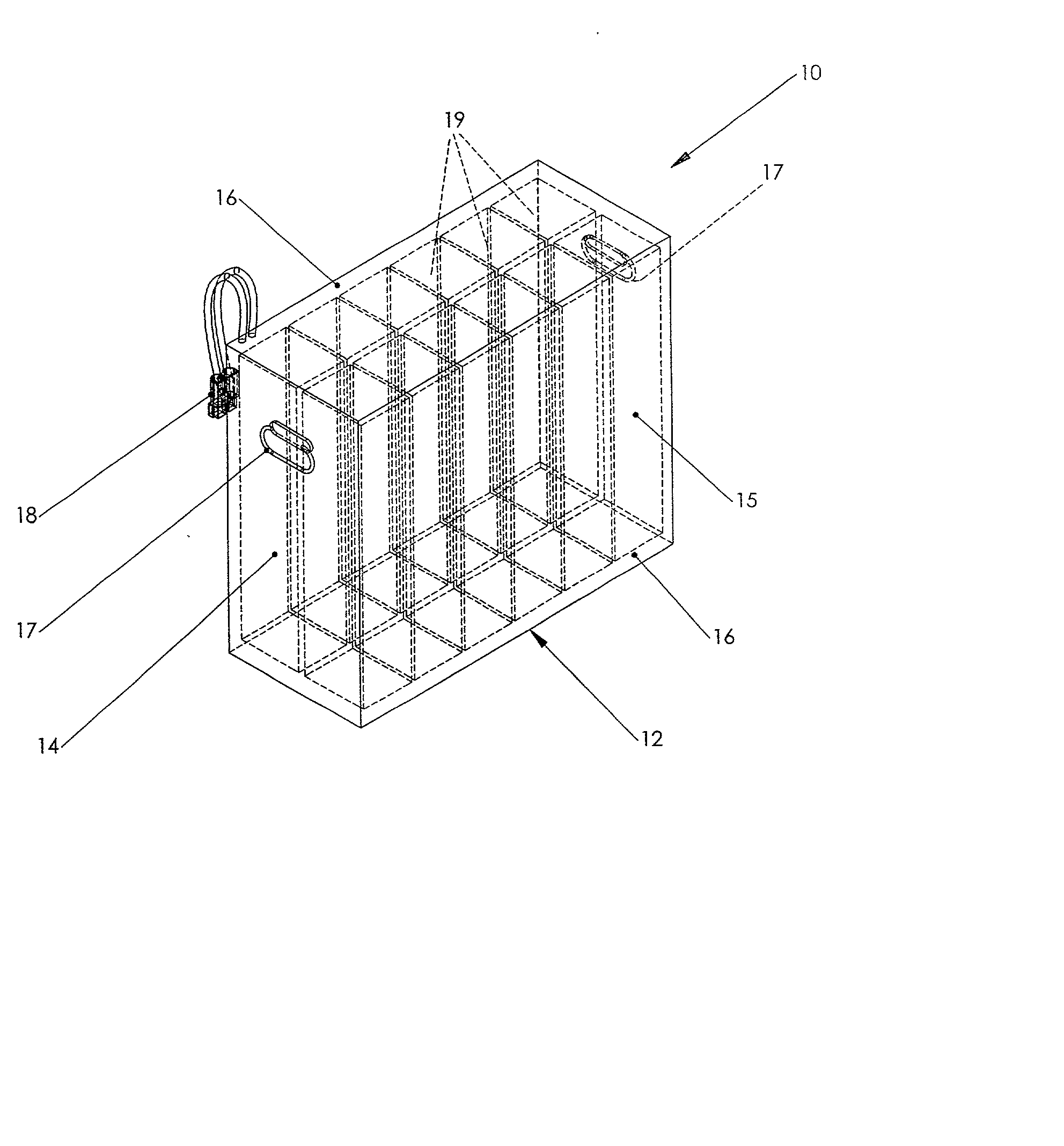
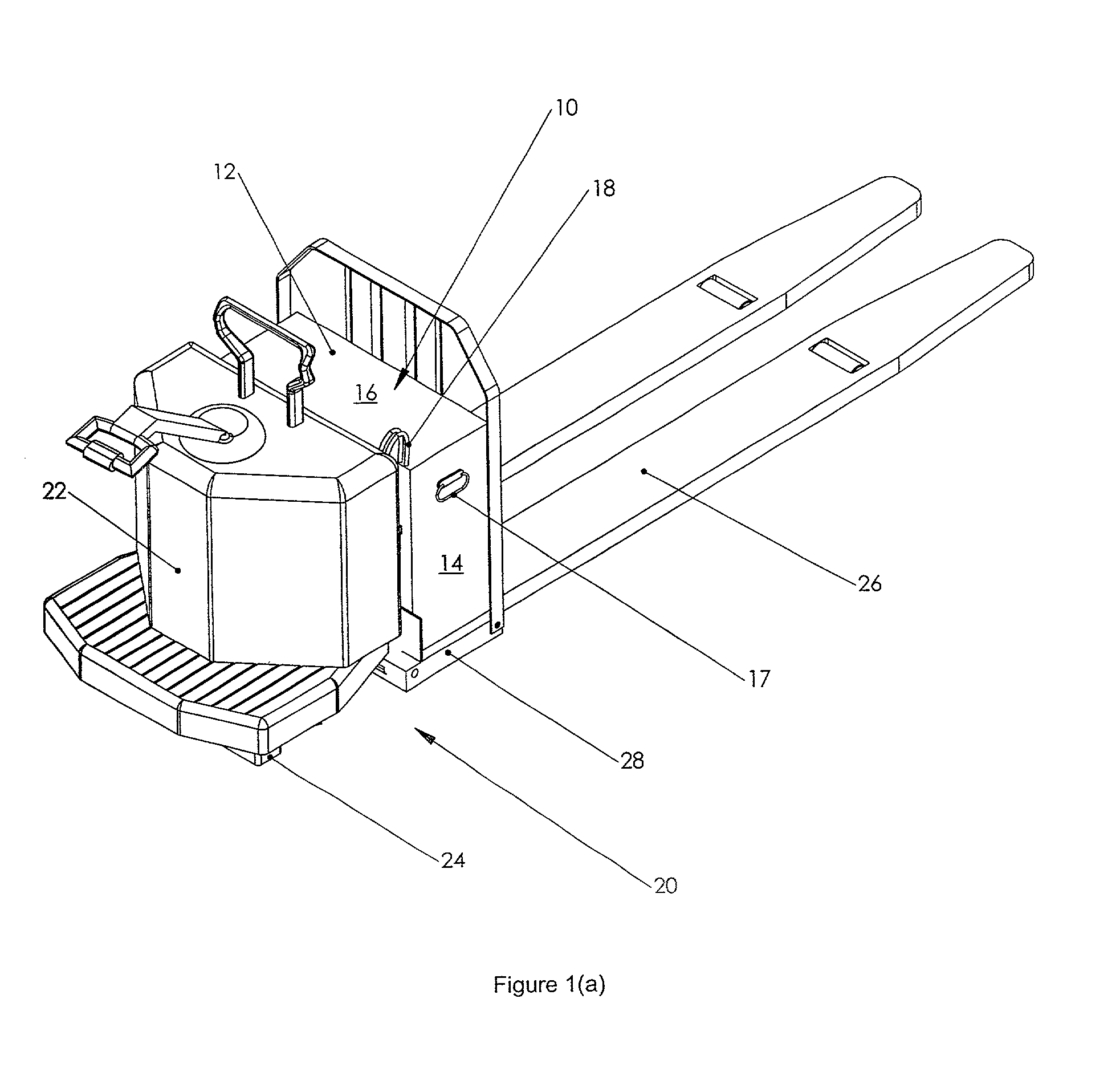
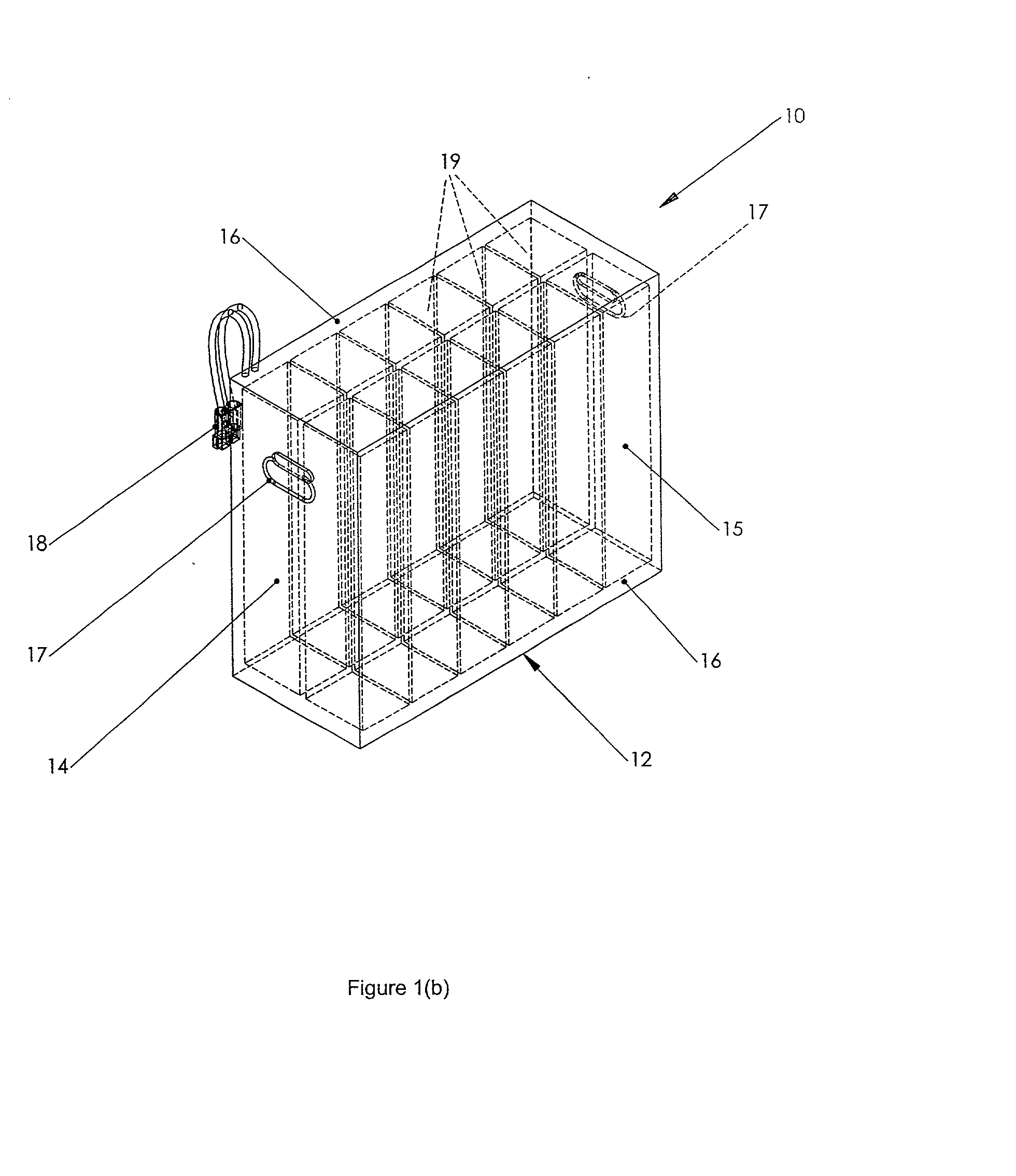
[0040] A conventional industrial or "traction" battery 10 for a forklift truck 20 is shown in FIGS. 1(a) and 1(b). Battery 10 includes a box-shaped housing 12 having opposed end faces 14, side faces 15 and top and bottom faces 16. As shown in FIG. 1(a), truck 20 typically includes a main body 22 mounted on wheels 24 and having a fork lift mechanism 26 attached. The main body 22 has a cavity or battery receptacle tray 28 which is sized and shaped to removably receive one battery 10. In the example shown, tray 28 is rectangular in shape and is located in the center of the main vehicle body 22. However, the location and dimensions of tray 28 will vary depending on the specific truck manufacturer, model and application. By way of example, pallet trucks have maximum allowable battery tray dimensions of 31"L.times.13"W.times.32"H (the height is variable depending upon the battery capacity). Narrow aisle lift trucks vary to a greater extent, but a typical battery tray 28, for a 36 volt DC ...


PUM

PropertyMeasurementUnit
temperatureaaaaaaaaaa
poweraaaaaaaaaa
poweraaaaaaaaaa

Abstract

This application relates to a hybrid power supply apparatus comprising a fuel cell and an energy storage device for use in off-road electric vehicles, such as lift trucks. The apparatus is a substitute for conventional lead acid batteries and is sized to fit within a conventional lift truck battery receptacle tray. The fuel cell and fuel processor systems are designed to meet the average load requirements of the vehicle, while the batteries and power control hardware are capable of responding to very high instantaneous load demands. The invention has a similar electrical interface as conventional battery systems and does not require vehicle modification. The apparatus is air-cooled to ensure that the hybrid power components operate within a preferred temperature range and to maintain the external surfaces of the apparatus and exhaust gases within safe temperature limits. Apart from vehicular applications, low power hybrid fuel cell products as exemplified by the present invention may also find application in uninterruptable power supply systems, recreational power, off-grid power generation and other analogous applications.

Description

[0001] This application relates to a hybrid power supply apparatus comprising a fuel cell and an energy storage device suitable for use in electric off-road vehicles, such as lift trucks and ground support equipment. The invention is a substitute for conventional lead acid batteries and is sized to fit within a standard electric vehicle battery receptacle tray. Other low power product applications are also described.[0002] Off-road electric vehicles, such as lift trucks, sweepers and scrubbers and ground support equipment, are used in a variety of commercial and recreational applications. By way of example, electric lift trucks comprising pallet forks are commonly used in retailing, wholesaling and manufacturing operations for lifting and moving materials inside warehouses and the like. Since lift trucks are often operated indoors, the use of internal combustion engines is precluded. In most cases lift trucks are battery powered to avoid potentially harmful emissions. Each battery i...

Claims


Application Information

Patent Timeline
Patent Type & Authority Applications(United States)
IPC IPC(8): B60L50/64B66F9/075H01M2/10H01M8/00H01M8/04H01M8/06H01M10/50H01M16/00
CPCB60K1/04Y02E60/50B60K2001/0455B60L11/005B60L11/1822B60L11/1877B60L11/1883B60L11/1887B60L11/1892B60L11/1894B60L2200/42B60Y2200/15B66F9/07572B66F9/07595H01M2/1083H01M8/00H01M8/04014H01M8/04373H01M8/04417H01M8/04567H01M8/04597H01M8/04701H01M8/04768H01M8/0491H01M8/0612H01M8/2475H01M10/5004H01M10/5016H01M10/5067H01M10/5071H01M10/5093H01M16/006Y02T10/7016Y02T10/7022Y02T10/705Y02T10/7072Y02T90/124Y02T90/14Y02T90/34B60K2001/005H01M10/625H01M10/6563H01M10/66H01M10/6565H01M10/613Y02P90/60B60L50/40B60L53/80B60L50/66B60L50/72B60L58/40B60L58/33B60L58/34Y02T10/70Y02T90/40Y02E60/10H01M50/249B60L50/64H01M50/209H01M50/267H01M50/296H01M50/242Y02T90/12
Inventor REID, CHRISTOPHER E.J.CORLESS, ADRIAN J.LEBOE, DAVIDLAWRENCE, CAROLYNKRATSCHMAR, KENNETH W.
Owner CELLEX POWER PRODS
Why Eureka
Try Eureka