This lithography method requires large-scale equipment, such as a vacuum apparatus, and complicated steps.
Therefore, the efficiency of use of the material is about several percentages, the most of the material have to be discarded, and the manufacturing cost can be expensive.
In other words, when the conductive fine particles are not overlapped, the portions where the conductive fine particles are not made contact with each other bring about breaks, etc.
Furthermore, when increase in thickness is insufficient, electrical resistance is increased and, therefore, the
conductivity of the wiring becomes inferior.
However, regarding the method in which the substrate is directly pattern-coated by the ink-jet method with the liquid containing conductive fine particles being dispersed, since the liquid containing conductive fine particles being dispersed is used, there is a limit of the quantity of the conductive fine particles that can be applied by
coating through
discharge of a fixed quantity of the liquid from the viewpoint of
viscosity, etc., during
discharge.
On the other hand, when it is intended to discharge the liquid in large quantities at a time, it becomes difficult to control the position of formation of the wiring.
In addition, the
line width of the wiring becomes large contrary to requirements for integration of electronic circuits, etc.
However, such a
bank has to be formed using
photolithography and, therefore, an increase in cost is brought about.
However, regarding this method, since a step of forming patterns of the lyophilic portion and the liquid-repellent portion by using a
mask, etc., is required and, in addition, a step of providing alignment marks for precisely applying a
coating on the lyophilic pattern is also required, the process becomes complicated.
In addition, since the discharge is performed onto the lyophilic portion and, the droplets spread, it becomes difficult to form a conductive film with an increased film thickness.
However, it becomes difficult to collect the liquid within the lyophilic portion unless the liquid-repellent property of the liquid-repellent portion with respect to the liquid is increased by a large degree.
Furthermore, the
line width of the wiring to be formed is limited to the width of the lyophilic portion of the substrate.
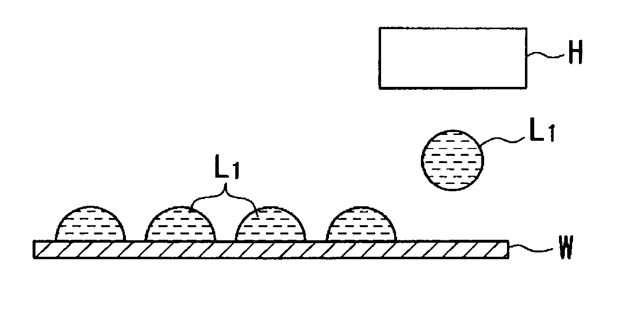
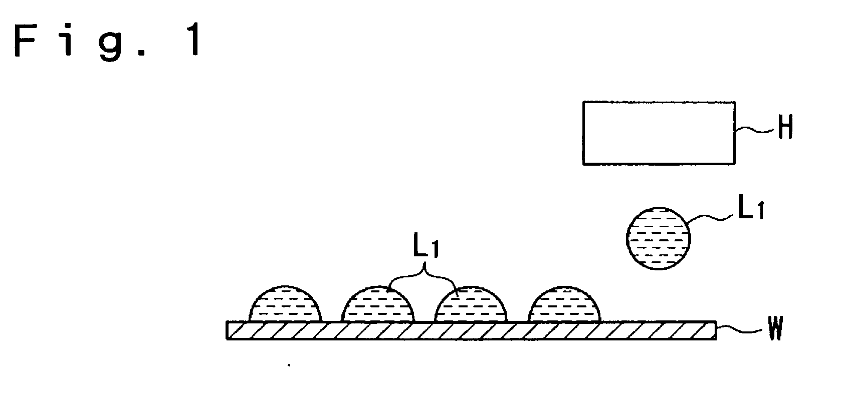
As described above, generation of the bulge brings about a fatal defect in performance of the conductive film wiring.
However, although the method according to the Japanese
Patent Application No. 2001-193679 prevented generation of the bulge, it did not exhibit an adequate effect of preventing the liquid containing conductive fine particles being dispersed from
wetting and spreading after being hit onto the substrate because the liquid-repellent property of the substrate was 60 degrees or less and was not so large.
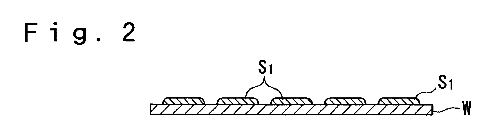
Furthermore, in the case where another coating was applied after the liquid was dried, since the liquid-repellent property of the substrate was 60 degrees or less and was not so large, difference in the liquid-repellent property from the portion which became lyophilic after the liquid was dried was not adequate.
Consequently, when the quantity of the liquid was excessive in application of another coating, there were problems in that the liquid did not remain at the portion where the liquid had been dried previously, and was likely to flow down to the substrate and, therefore, the line width was increased.
(1) Since a
vapor phase reaction is used, particles of
silicon are generated in the
vapor phase and, therefore, production yield is low due to
pollution of the apparatus and generation of foreign matters.
(3) Since the formation speed of the film is low, the productivity is low.
(4) In the
plasma CVD method, complicated and expensive high-frequency generators, vacuum apparatuses, etc., are required.
(5) Regarding
photolithography, the process is complicated, the efficiency of use of the
raw material is low, and large quantities of wastes, such as resists and etchants are generated.
In terms of the material, since gaseous
silicon hydride having high
toxicity and high reactivity is used, it is difficult to
handle and, in addition, a hermetically sealed vacuum apparatus is required because of the material being gaseous.
In general, these apparatuses are large-scale, the apparatuses themselves are expensive and, in addition, high cost of the product is brought about because a great deal of energy is consumed for a vacuum
system and a
plasma system.
However, regarding this method, since a step of forming patterns of the lyophilic portion and the liquid-repellent portion by using a
mask, etc., is required and, in addition, a step of providing alignment marks for precisely applying a coating on the lyophilic pattern is also required, the process becomes complicated.
In addition, although the silicon film pattern is required to also have a somewhat large film thickness in order to keep the uniformity of the film, since the discharge is performed onto the lyophilic portion, the droplets spread by
wetting and, therefore, it becomes difficult to increase the film thickness.
However, it becomes difficult to collect the liquid within the lyophilic portion unless the liquid-repellent property of the liquid-repellent portion with respect to the liquid is increased by a large degree.
However, regarding the properties of the discharged liquid by the ink-jet method, due to limitations such as
surface tension and
viscosity, it is practically difficult to adjust the
contact angle by adjusting only the properties of the liquid.
This is because when exceeding 0.1 .mu.m clogging of a
nozzle is likely to occur and, therefore, discharge by the ink-jet method becomes difficult.
In addition, this is because when less than 5 nm, the volume ratio of the coating agent with respect to the conductive fine particles is increased and, therefore, the ratio of the organic materials in the resulting film becomes excessive.
This is because when the
vapor pressure is higher than 200 mmHg, the dispersion medium vaporizes rapidly after being discharged and, therefore, it becomes difficult to form an excellent film.
This is because when the
vapor pressure is higher than 50 mmHg, clogging of a
nozzle due to
drying is likely to occur during discharge of the droplets by the ink-jet method and, therefore, it becomes difficult to discharge stably.
On the other hand, when the dispersion medium has a
vapor pressure of lower than 0.001 mmHg at
room temperature,
drying becomes slow so that the dispersion medium becomes likely to remain in the film and, therefore, a good-quality conductive film is unlikely to be produced after a heat and / or optical treatment in the later step.
This is because when the
surface tension is less than 0.02 N / m during discharge of the liquid by the ink-jet method, the wettability of an ink composition with respect to a
nozzle surface is increased and, therefore, a deviation in flight is likely to occur, and when the
surface tension exceeds 0.07 N / m, the shape of
meniscus at the nozzle tip is not stabilized and, therefore, it becomes difficult to control the quantity of discharge and timing of discharge.
This is because when the
viscosity is less than 1 mPa.multidot.s during discharge by the ink-jet method, the periphery of the nozzle is likely to be polluted due to bleeding of ink, and when the viscosity exceeds 50 mPa.multidot.s, the frequency of clogging of a nozzle hole is increased and, therefore, it becomes difficult to discharge droplets smoothly.
When less than 5, since the
silane compound itself becomes unstable due to warping of the region caused by the ring, it becomes difficult to
handle.
When n exceeds 20, reduction of
solubility resulting from the cohesion force of the
silane compound is observed and, therefore, selection of the
solvent to be used is limited.
When a+c is less than 5, since the
silane compound itself becomes unstable due to warping of the region caused by the ring, it becomes difficult to
handle.
When a+c exceeds 20, reduction of
solubility resulting from the cohesion force of the silane compound is observed and, therefore, selection of the
solvent to be used is limited.
This is because when the vapor pressure is higher than 200 mmHg, the
solvent vaporizes rapidly after being discharged and, therefore, it becomes difficult to form an excellent film.
This is because when the vapor pressure is higher than 50 mmHg, clogging of a nozzle due to
drying is likely to occur during discharge of the droplets by the ink-jet method and, therefore, it becomes difficult to discharge with stability.
On the other hand, when the solvent has a vapor pressure lower than 0.001 mmHg at
room temperature, drying becomes slow so that the solvent becomes likely to remain in the film and, therefore, a good-quality conductive film is unlikely to be produced after a heat and / or optical treatment in the later step.
This is because when the surface tension is less than 0.02 N / m during discharge of the liquid by the ink-jet method, the wettability of an ink composition with respect to a nozzle surface is increased and, therefore, a deviation in flight is likely to occur, and when exceeding 0.07 N / m, the shape of
meniscus at the nozzle tip is not stabilized and, therefore, it becomes difficult to control the quantity of discharge and timing of discharge.
This is because when the viscosity is less than 1 mPa.multidot.s during discharge by the ink-jet method, the periphery of the nozzle is likely to pollute due to bleeding of ink, and when the viscosity exceeds 50 mPa.multidot.s, the frequency of clogging of a nozzle hole is increased and, therefore, it becomes difficult to discharge droplets smoothly.
hat. When the temperature reached is less than 300.degree. C.,
thermal decomposition of the organic silicon compound does not advance adequately and, therefore, sometimes, a silicon film with an adequate thickness cannot be fo
Since the electronic device shown in FIGS. 10(a) to (c) is provided with the
liquid crystal device of the embodiment, problems such as breaks and short circuits in the wirings are unlikely to bring about and, in addition, it becomes possible to miniaturize and to slim.
The reason for this is considered that impartation of liquid repellency to the substrate was inadequate.

