Sensor and rolling bearing apparatus with sensor
a technology of sensor and rolling bearing, which is applied in the direction of bearing unit rigid support, instruments, transportation and packaging, etc., can solve the problems of increasing the number of sensors to be incorporated into the rotating support apparatus, troublesome mounting operation, and cumbersome routing of harnesses 32a, 32b, so as to improve the accuracy of abnormality detection of rolling bearings
- Summary
- Abstract
- Description
- Claims
- Application Information
AI Technical Summary
Benefits of technology
Problems solved by technology
Method used
Image
Examples
first embodiment
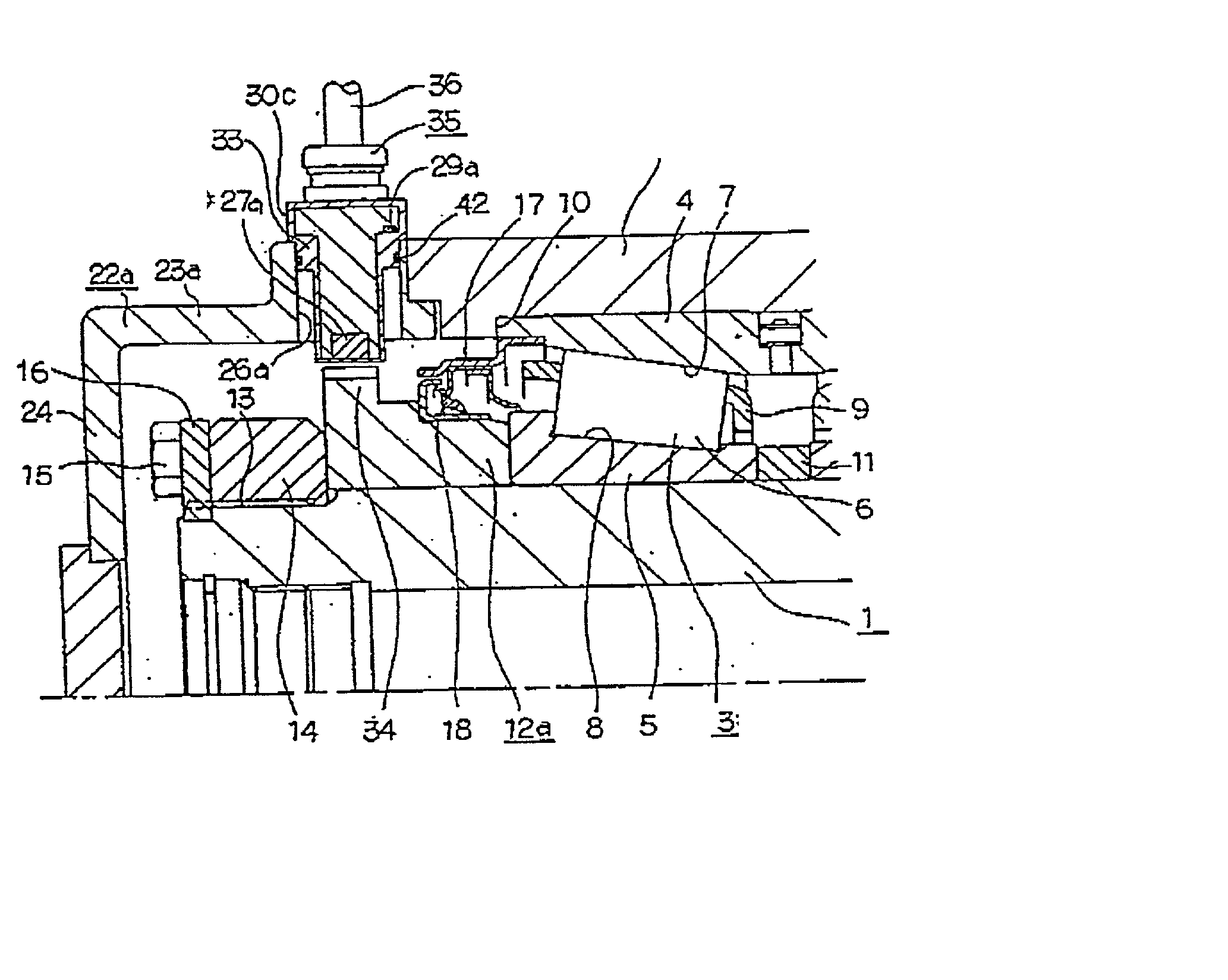
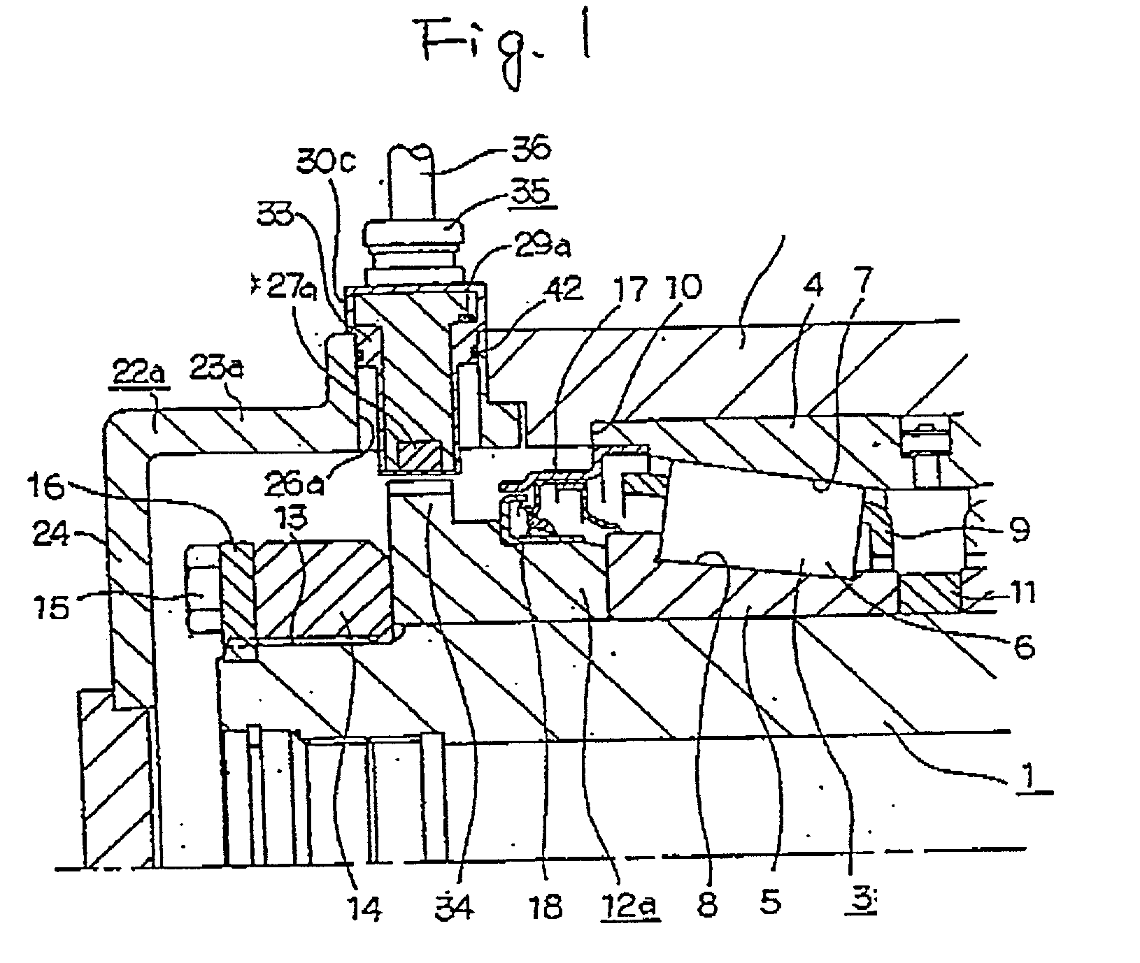
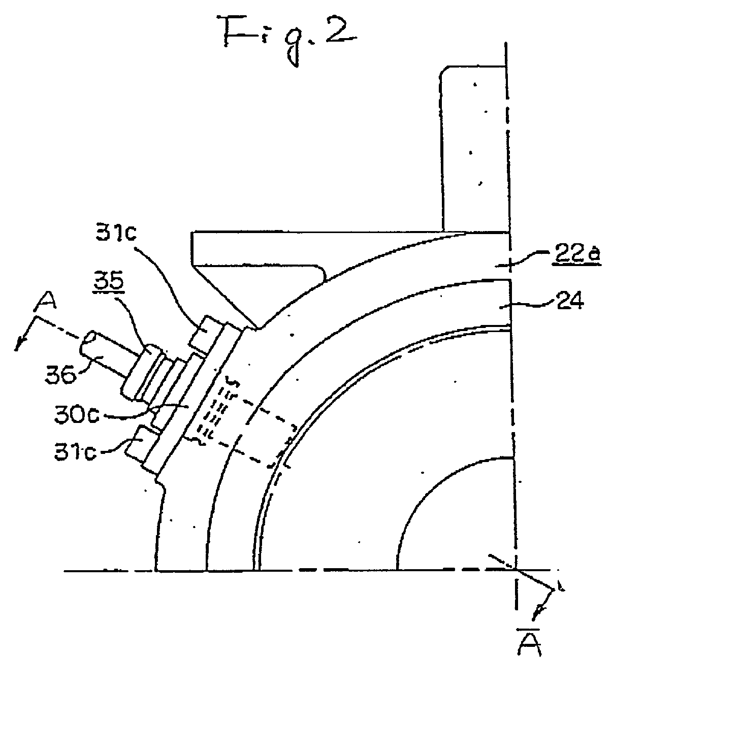
[0181] FIGS. 1 and 2 show the present invention. The present invention has a feature that a rotation speed sensor 27a for detecting the rotation speed of an axle shaft 1, which serves as a rotating shaft, and a temperature sensor 29a for detecting the temperature of a rolling bearing rotatably supporting the axle shaft 1 are retained in a single sensor holder 33 (sensor envelope), thereby solving the drawbacks of the related-art construction. In other respects, the present invention is identical in structure and operation with the rotating support apparatus of related-art construction shown in FIGS. 63 and 64. Hence, like parts are assigned like reference numerals, and explanations of overlapping features are omitted or simplified. Hereinbelow, descriptions of primarily the features of the present invention will be provided.
[0182] In the present invention, an outward flange section 34 is formed along the entire outer circumferential surface of an outer end section of an annular memb...
fifth embodiment
[0190] More preferably, the harnesses for acquiring signals output from the respective sensors 27a and 29a and a ground line for grounding purpose are stranded (twisted), thereby further diminishing influence of noise stemming from electromagnetic coupling. An effect of dampening influence of noise can be further increased, by means of individually shielding a twisted pair consisting of the stranded harnesses and the ground line or collectively shielding all the twisted pairs. Particularly, under the situation in which the rotation speed sensor 27a outputs a digital signal, when the harness for delivering a signal output from the rotation speed sensor 27a and the harness for delivering an analog signal output from the temperature sensor 29a (also a signal output from a vibration sensor to be incorporated into a fifth embodiment shown in FIG. 6, such as an acceleration sensor 40) are bundled into the single cable 36, the effect of stranding the harnesses for delivering the output sig...
second embodiment
[0192] FIG. 3 shows the present invention. In the present embodiment, the journal box 2a extends so as to surround the annular member 12a, and the sensor mount hole 26b is formed in the end section of the journal box 2a.
[0193] In contrast with the first embodiment, the present embodiment may encounter a disadvantage of processing of a sensor mount bearing surface or the sensor mount hole 26b becoming troublesome; a disadvantage of the axial dimension of the journal box 2a becoming larger, thereby rendering the rotating support apparatus heavier (increasing the dimension of the journal box rather than increasing the axial dimension of the cover tends to induce an increase the weight of a rotating support apparatus); or a disadvantage of an operation for removing and attaching the sensor unit 35 from and to the sensor mount hole 26b for maintenance and inspection purpose becoming troublesome to some degree. However, transfer of heat from the outer ring 4 constituting the double row ta...
PUM
 Abstract
Description
Claims
Application Information
 - R&D
- Intellectual Property
- Life Sciences
- Materials
- Tech Scout
- Unparalleled Data Quality
- Higher Quality Content
- 60% Fewer Hallucinations
Browse by: Latest US Patents, China's latest patents, Technical Efficacy Thesaurus, Application Domain, Technology Topic, Popular Technical Reports.
© 2025 PatSnap. All rights reserved.Legal|Privacy policy|Modern Slavery Act Transparency Statement|Sitemap|About US| Contact US: help@patsnap.com


