Method and instrumentation for micro dispensation of droplets

a droplet and micro-dispensing technology, applied in the direction of mixers, component separation, decorative arts, etc., can solve the problems of micro-fabrication procedures, tedious dispensing procedures, unreachable interconnection, etc., and achieve the effect of easy mass production

Inactive Publication Date: 2003-05-22
GYROS
View PDF7 Cites 53 Cited by
  • Summary
  • Abstract
  • Description
  • Claims
  • Application Information

AI Technical Summary

Benefits of technology

0044] The disc may be made from different materials, such as plastic material, glass, silicone etc. Polysilicone is included in plastic material. From the manufacturing point of view plastic material is many times preferred because this kind of material are normally cheap and mass production can easily be done, for instance by replication. Typical examples of replication techniques are embossing, moulding etc. See for instance WO 9116966 (Pharmacia Biotech AB, hman & Ekstrom). Replication processes typically result in open microchannel structures as an intermediate product which subsequently is covered by a lid, for instance according to the procedures presented in WO 0154810 (Gyros AB, Derand et al) or by methods described in publications cited therein. The proper hydrophilic / hydrophobic balance are preferably obtained according to the principles outlined in WO 0056808 (Gyros AB, Larsson et al) and WO 0147637 (Gyros AB, Derand et al). All three WO publications are hereby incorporated by reference.
0045] The microchannel structures (200) used in experiments 4-5 of the Experimental Part is given in FIG. 2. The arrow (201) indicates the upward direction and is directed towards the centre of the disc on which the structure is placed. The complete structure used in the experiments comprises a common distribution channel (202) with an inlet port (203) and an inlet microcavity (204) with parallel grooves / ridges (205) in the bottom, and an outlet port (206). Along the distribution channel (202) there is a number of Y-shaped structures (microchannel structures) (200) with one of the upward shanks (208) being connected to the distribution channel (202) and the other upward shank (209) comprising an inlet port (210) of the same kind as inlet port (203). The lower shank (211) of the Y-shaped structure contains an outlet port (212) opening to ambient atmosphere and has a shallow part (213) and a deeper part (214). The dual depth means that if a liquid containing particles with a larger diameter than the depth of the shallow part is transported through the structure, the particles will assembly as a packed bed in the deeper part (214) immediately upstream the shallow part (213). The common distribution channel (202) comprises vents (215) to ambient atmosphere between the individual microchannel structures. The inner surfaces of these vents are hydrophobized in order to prevent leakage of liquid. There are valves (216) in form of hydrophobized inner surfaces between each microchannel structure and the common distribution channel.

Problems solved by technology

This dispensation procedure is tedious and suffers from a number of drawbacks, in particular if dozens of microstructures have to be fed before spinning.
Interconnecting is tedious and has not yet been achieved in standard microfabrication procedures (Ellis Meng et al., "Micromachined fluidic couplers" and Aniruddha Puntambekar et al., "Self-aligning microfluidic interconnects with low dead volume" in Proceedings of .mu.-TAS 2000 Symposium May 14-18, 2000, Enschede, the Netherlands, Eds van den Berg et al., Kluwer Academic Publisher).
Dispensation of liquid aliquots during spinning is associated with targeting problems that are not at hand when the disc is resting because during spinning the target area is moving.

Method used


Image

  • Method and instrumentation for micro dispensation of droplets
  • Method and instrumentation for micro dispensation of droplets
  • Method and instrumentation for micro dispensation of droplets

Examples


experiment 1

[0099] Investigation of the Flow Profile Deformation Occurring Between the Pump and the Dispenser

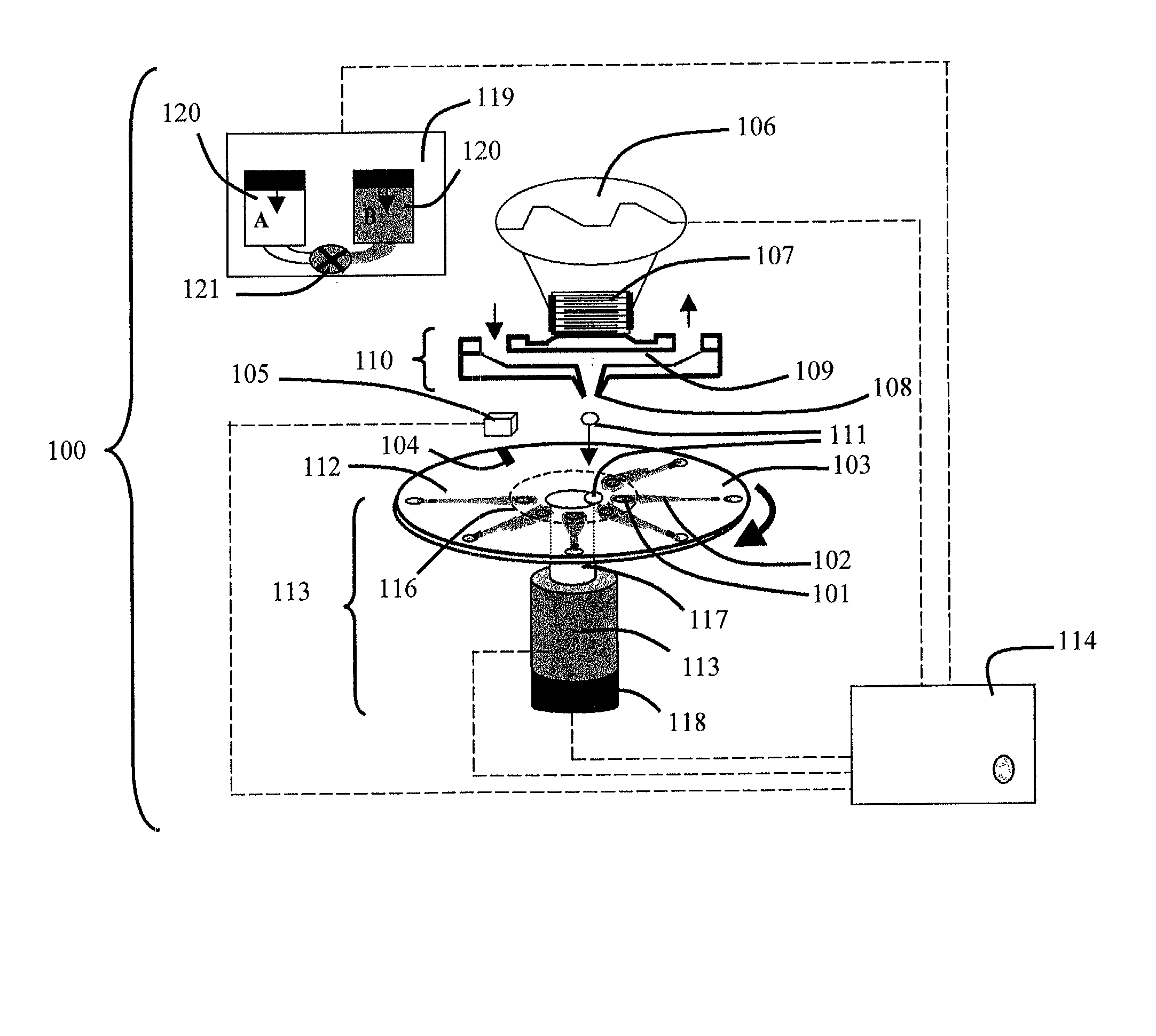
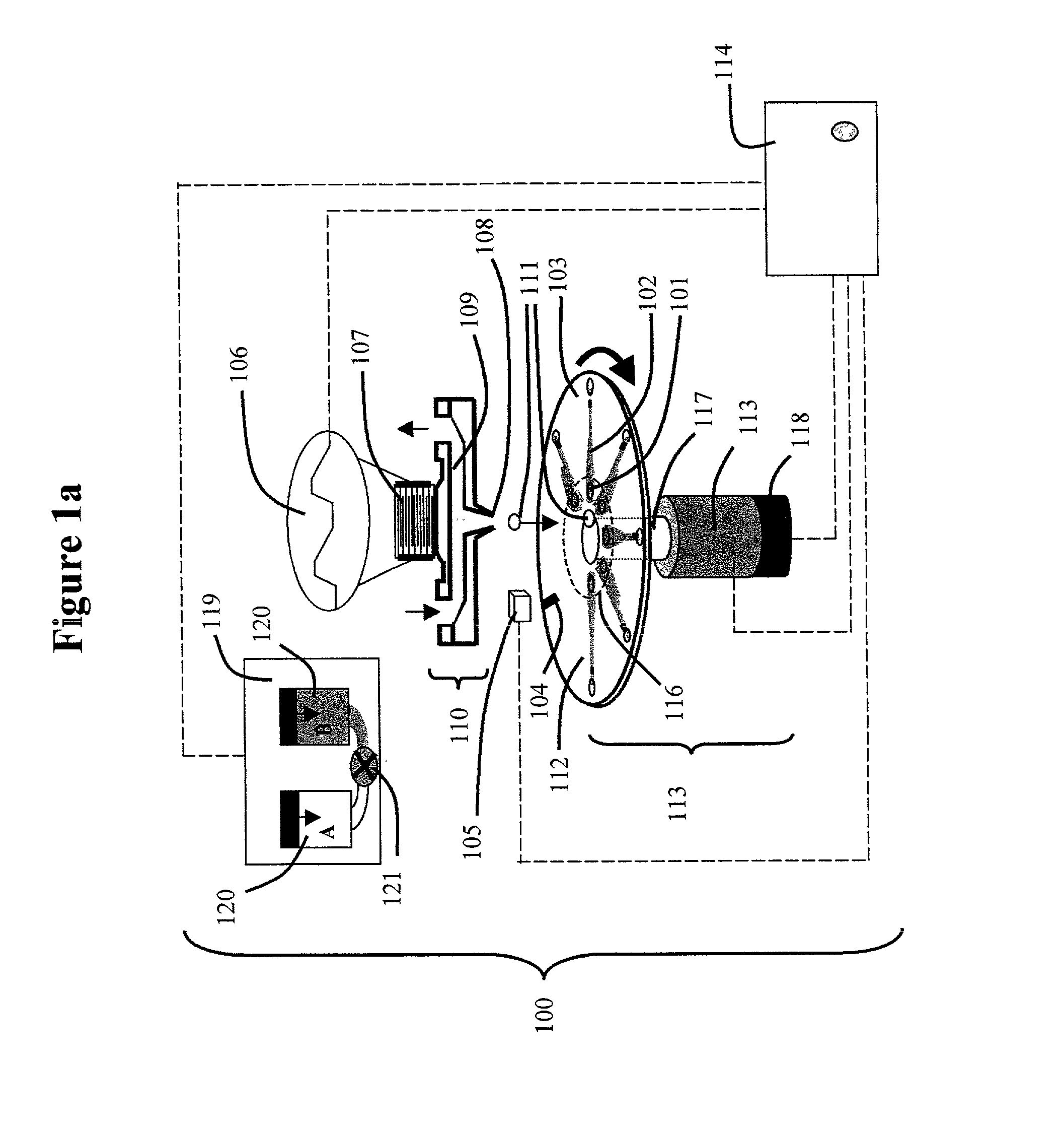
[0100] Experimental: The experimental set up was as in FIG. 1 except that the droplets were not collected in the microfluidic device. Colorimetry, with Cibacron dye (Brillant Red 4B-E, Ciba) in water was used to investigate gradients (from water up to 70% of the Cibacron solution applied over 1, 2 or 3 minutes) with different flow rates (0.1 and 0.5 ml / min). The process was monitored by collecting 500 droplets at predetermined intervals and measuring the colour intensity of the collected samples.

[0101] Results: FIG. 3 shows four gradients obtained from the dispenser. The result shown demonstrates the reproducibility of a 1 minute gradient at a flow rate of 0.3 ml / min. This graph shows that the gradient is obtained after 90 seconds indicating a lag time of 30s within the current configuration.

experiment 2

[0102] Velocity of the Droplet as a Function of the Gradient with a Constant Pulse

[0103] Experimental: The experimental set up was as in FIG. 1 except that the droplets were not collected in the microfluidic device. The variation in drop velocity v (m / s) with an acetonitrile gradient (0-80%) or a salt gradient 250 mM Tris-HCl pH 8 (0-1.5 M NaCl) was studied. The velocity was measured using a computer IR-camera system (Sydat Automation, Sweden) developed for evaluation of ink-jet print heads.

[0104] Results: Se FIG. 4. The physical properties of the dispensed liquid vary with the gradient profile and clearly affect the velocity of the droplets, leading to misalignment. However, this misalignment can be compensated for by adjusting various parameters, for example the trigger delay or the disc angular velocity (see equations 2 & 3) can be modified, although adjusting the angular velocity may affect flow control (see also FIG. 5).

[0105] For comparison when the disc is spun at 1500 rpm, ...

experiment 3

[0106] Velocity of the Groplet as a Function of the Pulse Amplitude

[0107] Experimental: The experimental set up was as in FIG. 1 except that the droplets were not collected in the microfluidic device. The drop velocity v (m / s) was studied as a function of the pulse amplitude for normal and high salt buffer solutions.

[0108] Results: By adjusting the pulse amplitude it is possible to adjust the drop velocity and thus to solve the misalignment problem.


PUM

PropertyMeasurementUnit
volumeaaaaaaaaaa
volumeaaaaaaaaaa
volumeaaaaaaaaaa

Abstract

A method for dispensing droplets of a liquid to a microsystem in the form of a disc comprising a target area (TA0I) in its surface, said disc preferably being a microfluidic disc comprising a microchannel structure with an inlet port that is a target area (TA0I). The method is characterized by comprising the steps of: i) providing (1) said disc which has a triggering mark, and (2) a dispenser arrangement comprising: a) a spinner for rotating the disc around its axis, b) a drop dispenser permitting dispensation of droplets to inlet port I, c) a fixed trigger position outside the disc, and d) a controller which is capable of triggering the dispensation of a droplet into (TA0I) as a function of the triggering mark passing the trigger position; ii) placing the disc in the spinner and programming the controller with values for dispensing parameters that will give dispensation of the droplets to TA0I; iii) dispensing the droplets. The invention also comprises the dispenser arrangement as such.

Description

[0001] The present invention concerns an interface between the macro and the micro world with respect to the dispensation of droplets of a liquid to one or more target areas (TA.sup.0I, TA.sup.1I, TA.sup.2I etc, array of target areas) on the surface of a disc. The target areas together with the disc define a microsystem for handling liquid aliquots in the microformat. The disc is preferably a microfluidic disc.[0002] Microformat in this context means that the liquid aliquots are in the microlitre (.mu.l) range. This range includes the nanolitre (nl) range which includes the picolitre (pl) range.BACKGROUND TECHNOLOGY AND PUBLICATIONS[0003] An increasing number of microsystems have been presented during the last decade. The main focus of microscaling has been the analytical and / or preparative performance of these microsystems and in practice very little attention has been paid on interfacing these microworlds with the surrounding macroworld. The present invention presents an interfaci...

Claims


Application Information

Patent Timeline
Patent Type & Authority Applications(United States)
IPC IPC(8): B01F5/06G01N35/00B01F13/00B01F15/02B01J4/02B01L3/00B05B3/10B67DG01N1/10G01N35/08G01N35/10G01N37/00
CPCB01F5/0646Y10T436/2575B01F5/0655B01F13/0059B01F15/0201B01F15/0233B01L3/5027B01L2200/027B01L2200/0605B01L2200/142B01L2300/0806B01L2300/16B01L2400/0409B01L2400/0418B01L2400/0633B01L2400/0688G01N35/00069Y10T436/25625Y10T436/119163Y10T436/111666Y10T436/115831B01F5/0647B01F25/4338B01F25/4331B01F25/433B01F33/30B01F35/71725B01F35/71
Inventor ANDERSSON, PERJESSON, GERALDSODERMAN, TOBIASSJOBERG, JAN
Owner GYROS
Why Eureka
Try Eureka