
Sensor apparatus

a technology of sensor and meter, which is applied in the field of sensor meter, can solve the problems of accelerating the aging and failure of electronic devices that are typically used in pressure and temperature, requiring extreme reliability of operation, and difficult and expensive to obtain multiple conductor cables

Inactive Publication Date: 2003-06-05
BAKER HUGHES INC
View PDF8 Cites 23 Cited by
  • Summary
  • Abstract
  • Description
  • Claims
  • Application Information

AI Technical Summary

Benefits of technology

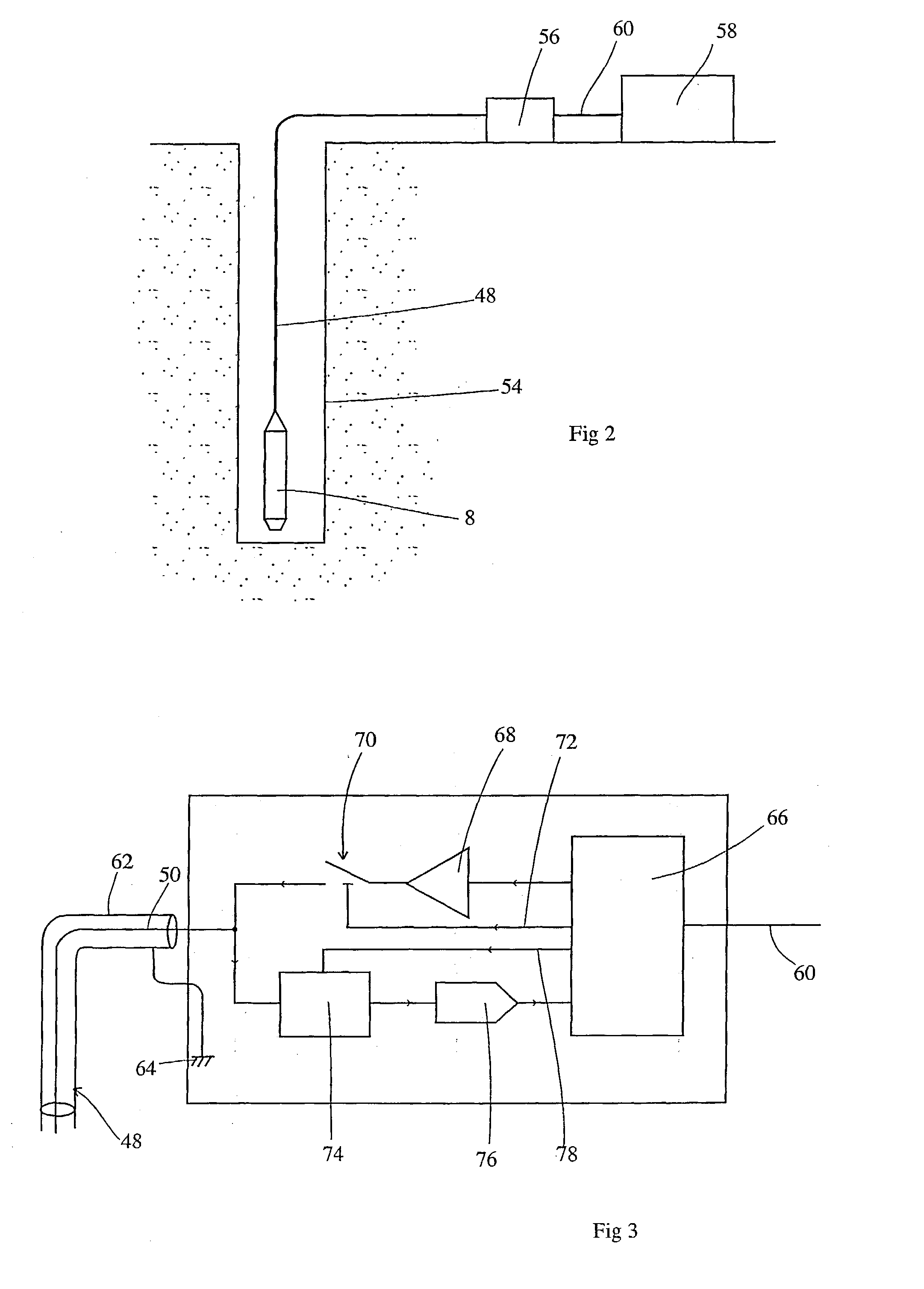
[0017] In a further embodiment of the present invention, the electrical drive signal is periodically interrupted, i.e. switched on and off. While the electrical drive signal is switched off, the remote instrumentation package can amplify the signal returned from the sensor, which will still be resonating provided the electrical drive signal was close to the resonant frequency prior to being switched off. This enables the signal from the sensor to be detected over very long cables.
[0019] Many types of electrically driven resonant sensors are known. The vibrating wire sensor disclosed in U.S. Pat. No. 4,255,973 is one example. Double ended tuning forks (DETFs) are also widely used. In this type of resonant sensor, each tine of the DETF vibrates in anti-phase so that the sensor is balanced. This can provide a relatively high Q factor and reduce the effect of outside influences on the sensor. The resonating element of the sensor is typically made of steel, although quartz and silicon have the well known benefits of low drift and very high "Q" factor. Typically resonators are driven either electromagnetically as in the case of U.S. Pat. No. 4,255,973, or using piezoelectric drivers known as PZTs, or the natural piezoelectric effect that occurs in quartz crystals.

Problems solved by technology

Many of these environments are also characterized by inaccessibility, and the need for extreme reliability of operation.
The high temperatures that are often encountered at the bottom of oil or gas wells accelerate the aging and failure of electronic devices that are typically used in pressure and temperature gauge instrumentation.
However, they require multiple insulated electrical conductors from the surface to the downhole sensors.
It is difficult and expensive to obtain multiple conductor cable that is reliable in an oil or gas well, and the multiple pin connectors that are consequently required in the installation are also a source of high cost and potential unreliability.
Whilst this method admirably eliminates electronics from the sensor, it only enables one sensor to be activated per cable.
In addition, the system does not appear well adapted for long distance use.
It seems that although double-ended tuning fork are known as such for other purposes, their advantages in borehole use have never been appreciated.
Such electronics is vulnerable and places a limitation on the equipment life and operating temperature.

Method used


Image

  • Sensor apparatus
  • Sensor apparatus
  • Sensor apparatus

Examples


Embodiment Construction

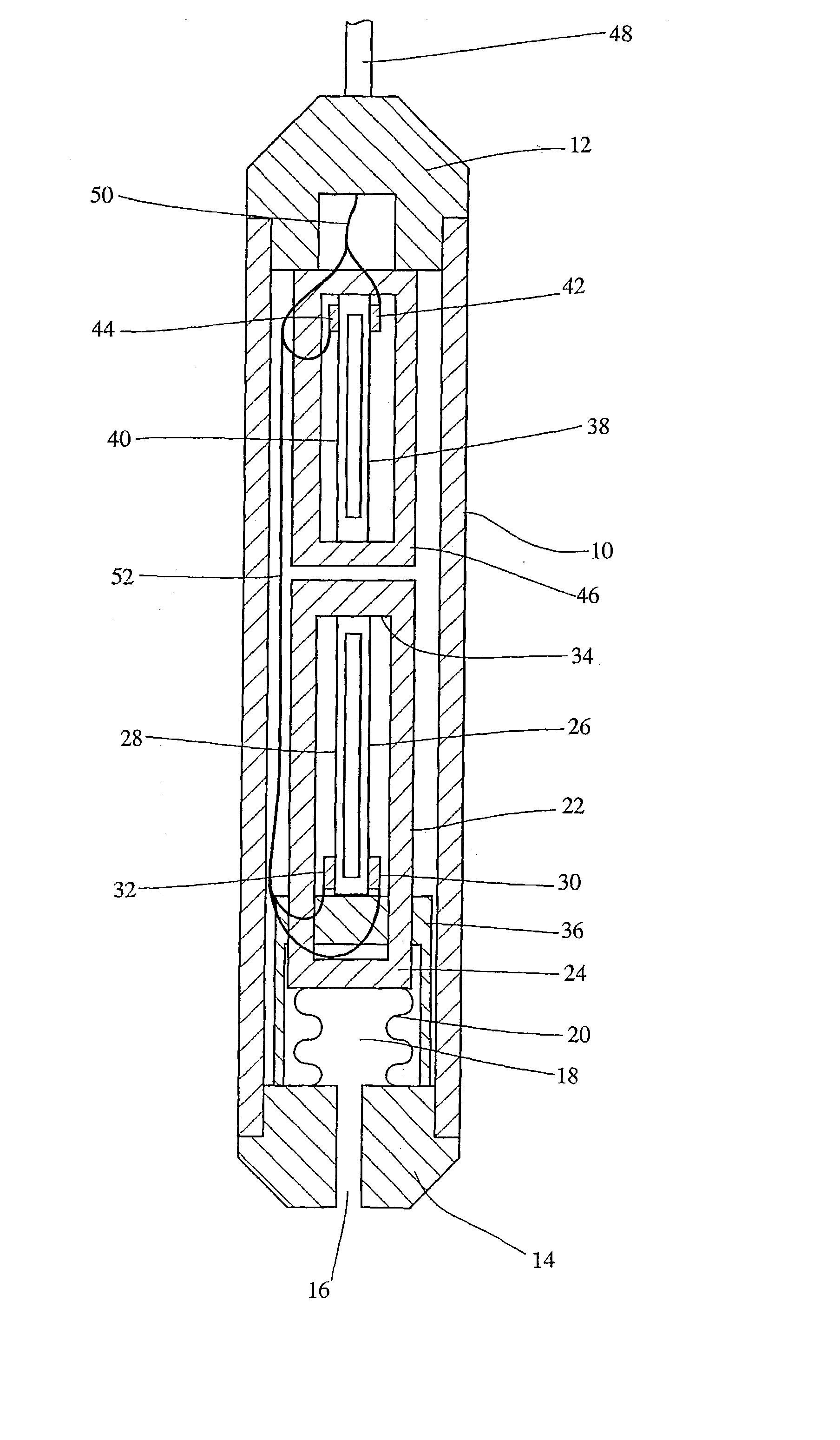
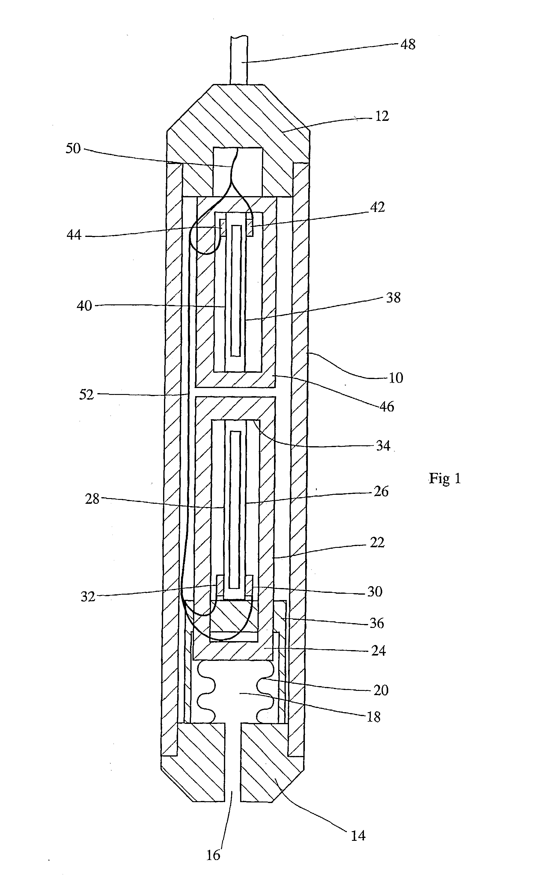
[0025] FIG. 1 shows a pressure and temperature gauge for use in oil and gas wells. A cylindrical pressure housing 10 is electron beam welded to a cablehead 12 at an upper end and a plug 14 at a lower end. In this description, upper and lower refer to orientations when the device is in its normal operating state within a well. This forms a sealed chamber that can withstand the high pressures required for this form of gauge. The fluid in the oil or gas well can enter via a pressure inlet 16 in the plug 14 and into an expansion volume 18 enclosed by bellows 20 sealed to the plug 14 at their lower end and to the base 24 of a closed-ended cylinder 22 at their upper end.

[0026] A pair of tines 26, 28 form a double ended tuning fork that is driven to vibrate in antiphase by a corresponding pair of PZT devices 30, 32. The fork thus formed is located within the cylinder 22, the upper end of the fork being attached to the inner face 34 of the upper end of the cylinder 22. The lower end of the ...


PUM

PropertyMeasurementUnit
pressureaaaaaaaaaa
resonant frequencyaaaaaaaaaa
temperatureaaaaaaaaaa

Abstract

A measurement head particularly for borehole use can measure multiple parameters with no electronics in the head and only a single conductor cable. Double-ended tuning forks (26, 28 and 38, 40) in the head are arranged to respond to different parameters such as temperature and pressure by adjusting their resonant frequencies. A drive signal on the conductor (50) is applied to transducers (30, 32, 42, 44) on all the tuning forks and those whose instantaneous resonant frequency is close will resonate. The signal is removed and the transducers return a decaying signal at the resonant frequency along the conductor. Other drive frequencies are tried, to locate the other sensors whose frequency ranges are separate.

Description

[0001] The present application relates to sensor apparatus. It seeks to address the long term reliability of such sensors when operated in adverse environments such as elevated temperatures or high radiation levels. The application is applicable (inter alia) to the measurement of physical parameters such as pressure, temperature and force, especially in high temperature environments.BACKGROUND TO THE INVENTION[0002] It is often desirable to measure pressure, temperature and force in environments that have very high ambient temperatures, such as at the bottom of oil or gas wells, inside nuclear reactors, or inside jet engines. Many of these environments are also characterized by inaccessibility, and the need for extreme reliability of operation. For example, the pressure and temperature at the bottom of an oil or gas well can be used to monitor the performance of the hydrocarbon reservoir. This information can aid the management of the production of that reservoir to maximise returns...

Claims


Application Information

Patent Timeline
Patent Type & Authority Applications(United States)
IPC IPC(8): E21B47/06E21B47/12G01L9/00
CPCE21B47/06E21B47/065Y10S73/01G01L9/0022E21B47/12E21B47/07
Inventor ATHERTON, ERIC
Owner BAKER HUGHES INC
Learn More