Micromechanical structure, in particular for an acceleration sensor or yaw rate sensor and a corresponding method for producing the same

a micromechanical and sensor technology, applied in the direction of acceleration measurement using interia forces, instruments, coatings, etc., can solve the problems of reducing the mechanical functional area, ignoring the attention, and limiting the application of micromechanical structures

Inactive Publication Date: 2003-06-26
ROBERT BOSCH GMBH
View PDF3 Cites 14 Cited by
  • Summary
  • Abstract
  • Description
  • Claims
  • Application Information

AI Technical Summary

Benefits of technology

0029] The underlying idea of the present invention is that the centrifugal mass has a certain structure with clearances, which can be made deflectable by etching a sacrificial layer underneath it. The sacrificial layer is present in a first area located underneath the centrifugal mass with a first etchable thickness and in a second area located underneath the centrifugal mass with a second etchable thickness, the second thickness being greater than the first thickness. The centrifugal mass is structured in the first area so that in etching only a maximum of two etching fronts may come together in order to limit etching residue deposits.

Problems solved by technology

However, contaminants 70 may cause a problem when they are not attacked during selective etching of sacrificial layer 50 or when they react with the etching medium forming non-soluble and / or non-volatile compounds as residues.
This creates the danger of these particles blocking the deflection of centrifugal mass 30 in the z direction or of producing an electrical short circuit therewith.
However, if three or more etching fronts come together, high particle structures may form, which greatly reduce the mechanical functional area.
Previously, attention was only paid to optimum underetching or free etching of the mechanical structure, but not to possible etching residues.
The formation of etching residues at the above-mentioned points in the sensor design represents a problem in particular in z-sensitive components in which sacrificial layer 50 is removed in a dry, isotropic etching step.
Here they cannot be detached or rinsed away by a liquid phase of the etching medium.

Method used


Image

  • Micromechanical structure, in particular for an acceleration sensor or yaw rate sensor and a corresponding method for producing the same
  • Micromechanical structure, in particular for an acceleration sensor or yaw rate sensor and a corresponding method for producing the same
  • Micromechanical structure, in particular for an acceleration sensor or yaw rate sensor and a corresponding method for producing the same

Examples


first embodiment

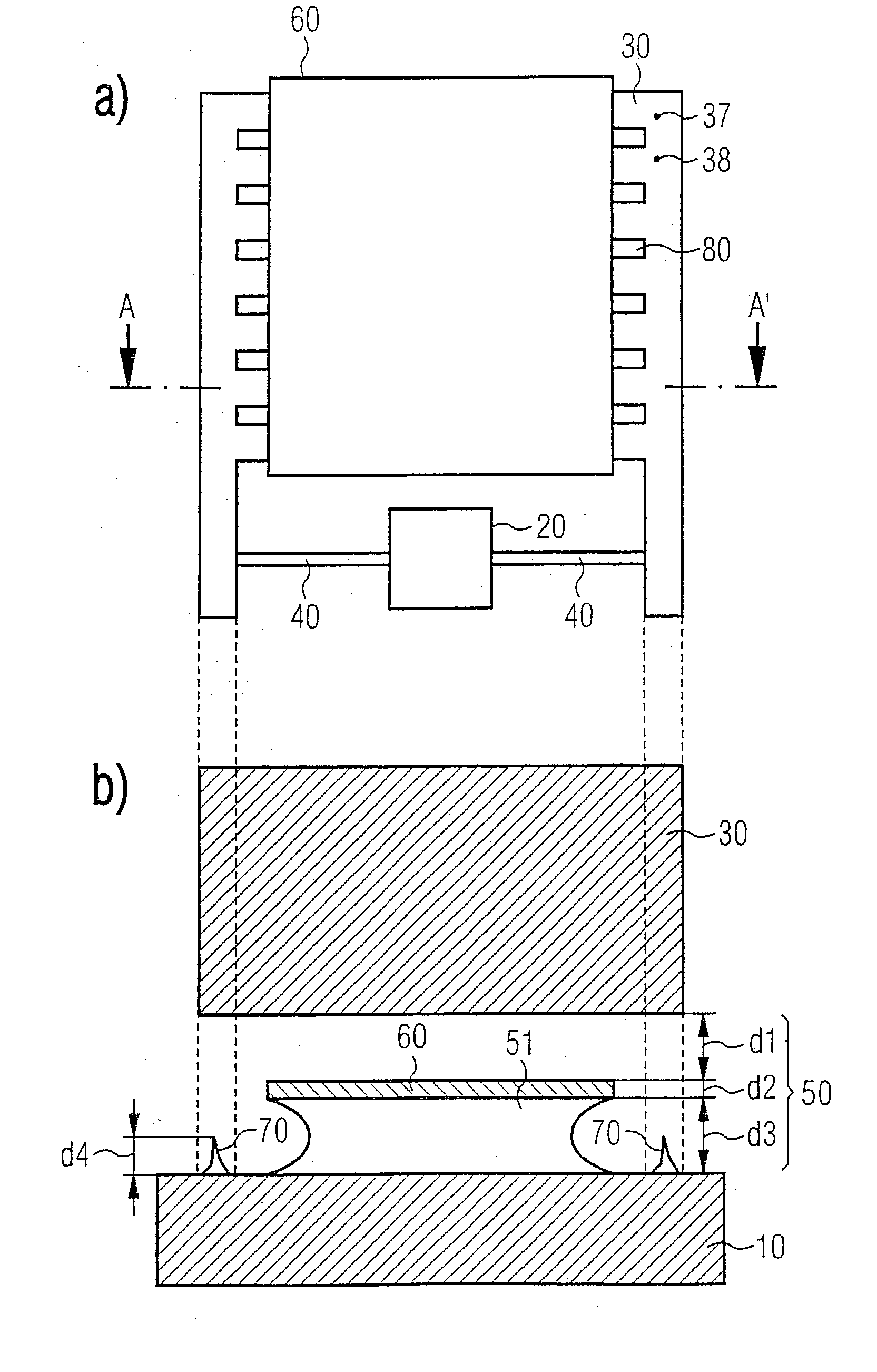
[0043] FIG. 1 shows a schematic top view of the micromechanical structure according to the present invention in the form of a rocker structure; specifically, FIG. 1a shows a top view, and FIG. 1b shows a section along line A-A'.

[0044] The structure according to FIG. 1 includes a substrate 10, which has an anchoring device 20 and a centrifugal mass 20 in the form of a rocker having longitudinal and transverse bars and corresponding clearances 80, which is connected to anchoring device 20 via a flexible spring device 40, so that centrifugal mass 30 is elastically deflectable from its rest position.

[0045] As in the case of the structure according to FIG. 6, deflectability is implementable in this embodiment by etching sacrificial layer 50 situated under centrifugal mass 30. Sacrificial layer 50 has a lower sacrificial sublayer 51 and an upper sacrificial sublayer 52, between which electrode areas 60 are provided, which electrostatically cooperate with centrifugal mass 30.

[0046] In this...

second embodiment

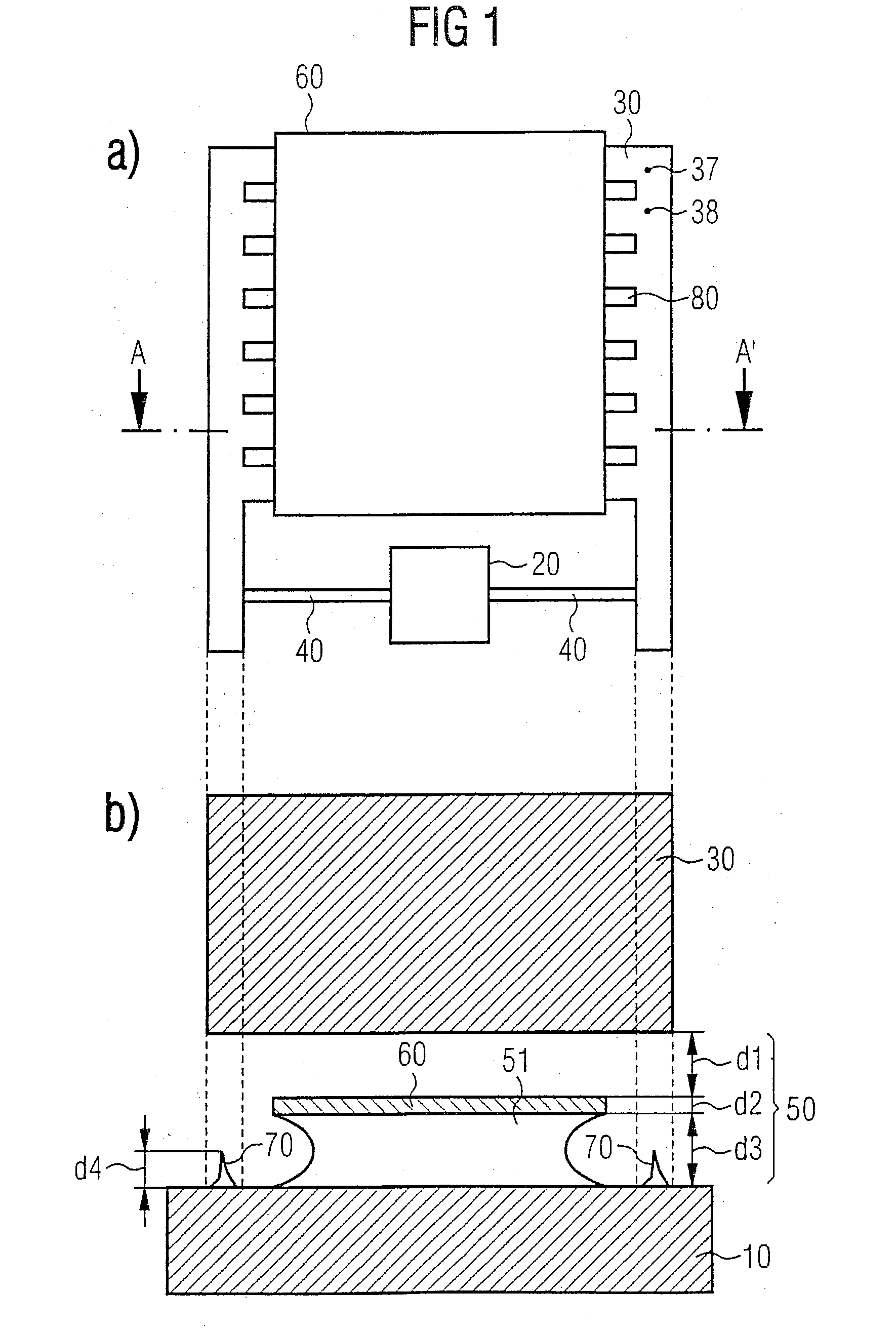
[0052] FIG. 2 shows a schematic top view of the micromechanical structure according to the present invention in the form of a rocker structure; specifically, FIG. 2a shows a top view of a first bar geometry, and FIG. 2b shows a top view of a second bar geometry.

[0053] In the second embodiment according to FIG. 2a, a first electrode area 60a, a second electrode area 60b, and a conductive shielding electrode area 90 as electrically functional layers are located in the printed conductor plane under the electromechanically effective structures. The electromechanically functional components include longitudinal bars and transverse bars which connect them and which do not end or bend or intersect over the electrode areas of the printed conductor plane, i.e., 60a, 60b, 90. Corner points 37 and points of intersection 38 are located next to lower electrode areas 60a, 60b, 90.

[0054] The transverse bars are divided into groups running over a lower electrode area 60a, 60b, 90. Within a group, t...

third embodiment

[0056] FIG. 3 shows a schematic top view of the micromechanical structure according to the present invention in the form of a rocker structure.

[0057] In this additional embodiment, lower electrode surfaces 1, 2, 3 underneath the electromechanical structures may be divided, so that points of intersection 38 of the transverse bars of the upper functional layer are located above the clearances left open between lower electrode areas 60c-60h. In addition, electrode areas 60c, 60d, as well as 60e, 60f, and 60g are connected to one another in pairs via a printed conductor 61.


PUM

PropertyMeasurementUnit
thicknessaaaaaaaaaa
thicknessaaaaaaaaaa
angleaaaaaaaaaa

Abstract

A micromechanical structure and a corresponding manufacturing method are described. The structure includes a substrate (10), which has an anchoring device (20), and a centrifugal mass (30), which is connected to the anchoring device (20) via a flexible spring device (40), so that the centrifugal mass (30) is elastically deflectable from its rest position. The centrifugal mass (30) has clearances and is designed to be deflectable by etching a sacrificial layer (50) underneath it. The sacrificial layer (50) is present in a first area located underneath the centrifugal mass (30) with a first etchable thickness (d1), and in a second area located underneath the centrifugal mass (30) with a second etchable thickness (d1+d2+d3), the second thickness being greater than the first thickness (d1). The centrifugal mass (30) is structured in the first area so that in etching only a maximum of two etching fronts may come together in order to limit the etching residue deposits.

Description

BACKGROUND INFORMATION[0001] The present invention relates to a micromechanical structure, in particular for an acceleration sensor or rotational speed sensor, having a substrate, which has an anchoring device and a centrifugal mass, which is connected to the anchoring device via a flexible spring device, so that the centrifugal mass is elastically deflectable from its rest position. The present invention also provides a manufacturing method for said micromechanical structure.[0002] Although it is usable on any micromechanical structure, the present invention and the problem on which it is based will be described in relation to a micromechanical rocker structure for an acceleration sensor or rotational speed sensor.[0003] FIG. 6 shows a schematic top view of a known micromechanical structure in the form of a rocker structure for an acceleration sensor or rotational speed sensor; FIG. 6a shows the micromechanical structure in top view and FIG. 6b in a sectional view along line C-C'.[...

Claims


Application Information

Patent Timeline
Patent Type & Authority Applications(United States)
IPC IPC(8): B81B3/00B81C1/00G01C19/5755G01P15/08G01P15/125H01L29/84
CPCG01C19/5755G01P15/125G01P15/0802G01P2015/0831
Inventor FRANZ, JOCHENILLING, MATTHIASHENNING, FRANKFISCHER, FRANKHEIN, PETER
Owner ROBERT BOSCH GMBH
Why Eureka
Try Eureka