Atomizing nozzle

a technology of atomizing nozzle and nozzle, which is applied in the direction of burners, combustion types, combustion processes, etc., can solve the problem that conventional evaporators are unable to instantaneously generate the proper quantity of gaseous reactants

Inactive Publication Date: 2003-07-17
ROBERT BOSCH GMBH
View PDF6 Cites 7 Cited by
  • Summary
  • Abstract
  • Description
  • Claims
  • Application Information

AI Technical Summary

Problems solved by technology

Because hydrogen refueling and storage in the motor vehicle remains a problem, hydrogen is produced directly on-board as needed in an upstream reformer stage from easy-to-handle fuels such as methanol, methane, diesel oil or gasoline and consumed immediately.
However, problems arise during the col

Method used


Image

  • Atomizing nozzle
  • Atomizing nozzle

Examples


Embodiment Construction

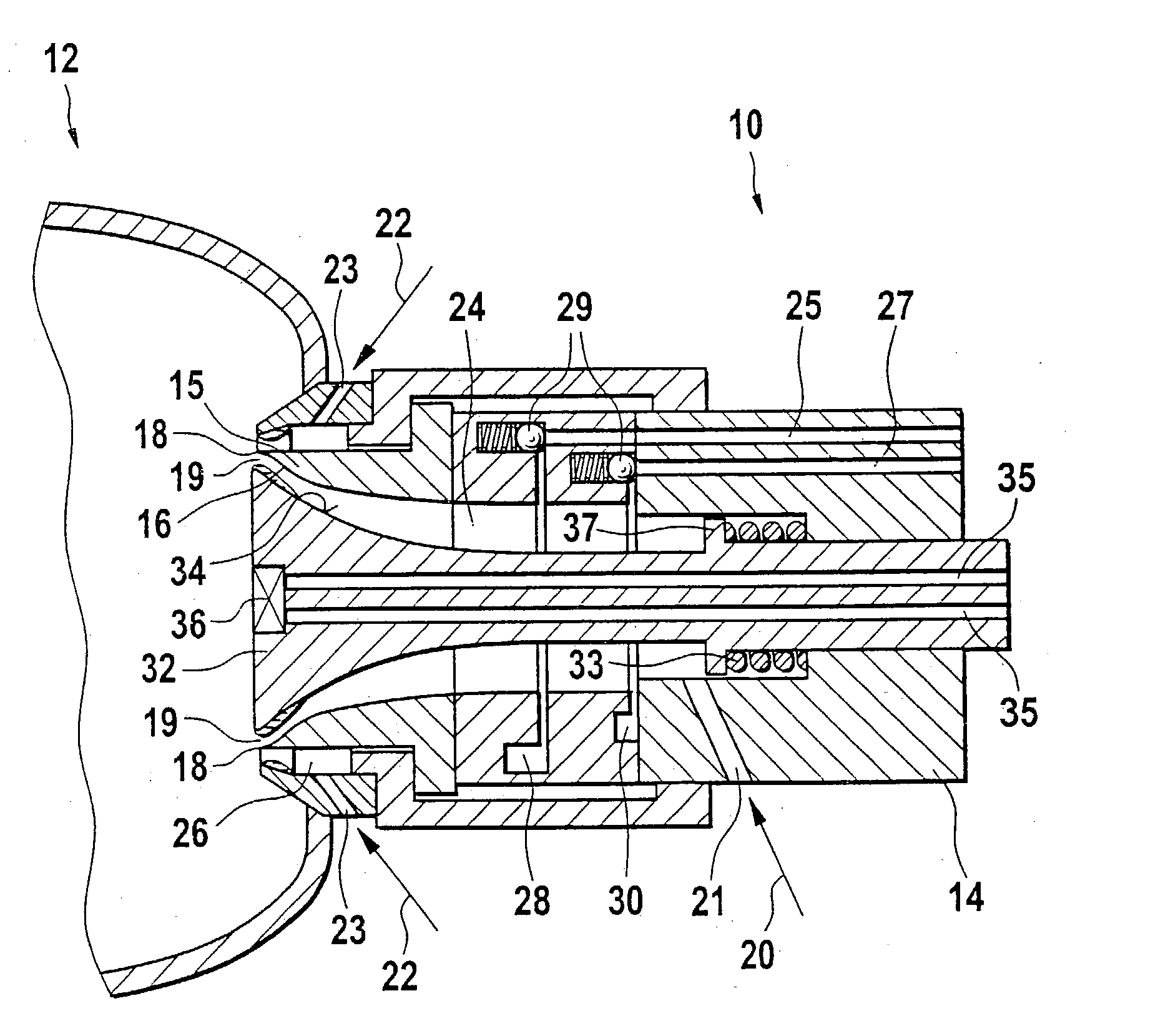
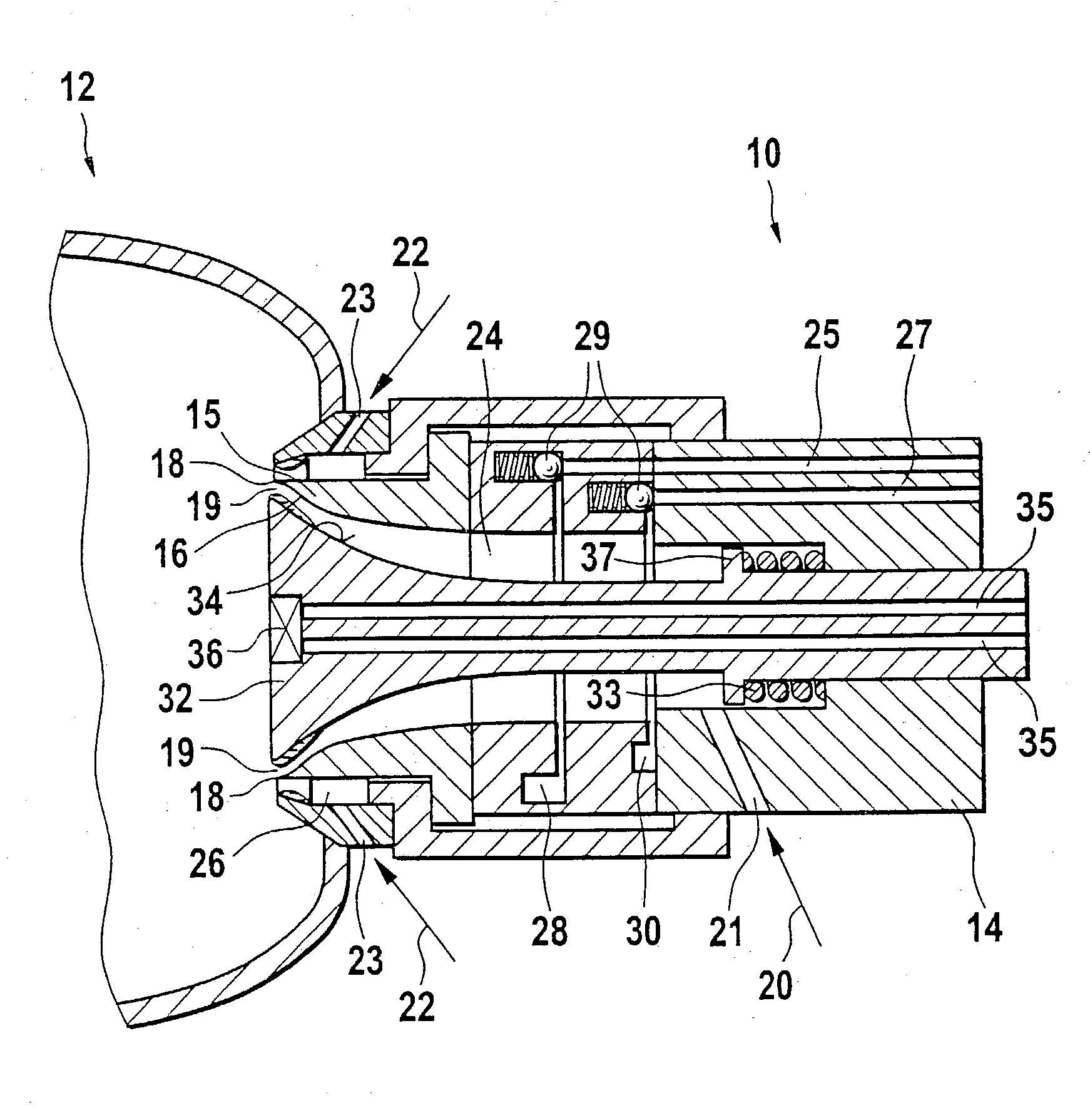
[0017] FIG. 1 shows a cross section of atomizing nozzle 10 according to the present invention, which is provided in a reactor wall of a partially illustrated chemical reformer 12.

[0018] Atomizing nozzle 10 includes a housing 14 which has an outlet 19 on the reactor side. Outlet 19 is designed, for example, with an annular shape. A first chamber 24, into which at least one first gas supply line 21 which supplies a first gas flow 20 to chamber 24 empties, is located in housing 14. A first liquid supply line 25 and a second liquid supply line 27, which supply liquid educts to chamber 24, are provided downstream and empty into first chamber 24. To prevent subsequent liquid leakage, liquid supply lines 25, 27 are equipped with spring-loaded non-return valves 29.

[0019] Annular gaps 28, 30, which enable the outflowing liquid to wet entire wall 16 of chamber 24, are provided at the outlets of liquid supply lines 25, 27. Wall 16 of chamber 24, which is covered by the liquid film, is delimite...


PUM


Abstract

Atomizing nozzle for introducing a gas/liquid mixture into a chemical reformer to produce hydrogen, having at least one gas supply line (21) for a gas stream (20), at least one liquid supply line (25, 27) and at least one outlet (19) for the atomized gas/liquid mixture as well as a first chamber (24) into which the liquid supply line (25, 27) empties, with the chamber (24) having a chamber wall (16) that forms a lip (18) at the outlet end, on both sides of which a separate gas flow (20, 22) is supplied.

Description

[0001] The present invention relates to an atomizing nozzle, in particular for introducing a gas / liquid mixture into a chemical reformer according to the definition of the species in claim 1.BACKGROUND INFORMATION[0002] Among the alternative drive concepts for motor vehicles, fuel cell-supported systems, in particular, are currently generating a great deal of attention. These systems typically include PEM (polymer electrolyte membrane) fuel cells that operate with hydrogen and air as the energy carriers.[0003] Because hydrogen refueling and storage in the motor vehicle remains a problem, hydrogen is produced directly on-board as needed in an upstream reformer stage from easy-to-handle fuels such as methanol, methane, diesel oil or gasoline and consumed immediately. The reformers employed for this purpose are chemical reactors that are used to partially oxidize the fuels by adding air and moisture, for example at a temperature of 800.degree. C., in catalytic converters, producing hyd...

Claims


Application Information

Patent Timeline
IPC IPC(8): B05B7/04B05B7/06
CPCB05B7/0416B05B7/1281B05B7/067
Inventor NAU, MICHAELRUOFF, MANFREDBAREIS, MARCILGNER, FRANK
Owner ROBERT BOSCH GMBH
Why Eureka
Try Eureka