
Permanent magnet synchronous motor driving system, and method of testing permanent magnet synchronous motor driving system

a permanent magnet synchronous motor and driving system technology, applied in the direction of dynamo-electric converter control, dynamo-electric gear control, elevators, etc., can solve the problems of easy leakage current, and high frequency of leakage curren

Inactive Publication Date: 2003-07-17
MEIDENSHA ELECTRIC MFG CO LTD
View PDF9 Cites 5 Cited by
  • Summary
  • Abstract
  • Description
  • Claims
  • Application Information

AI Technical Summary

Benefits of technology

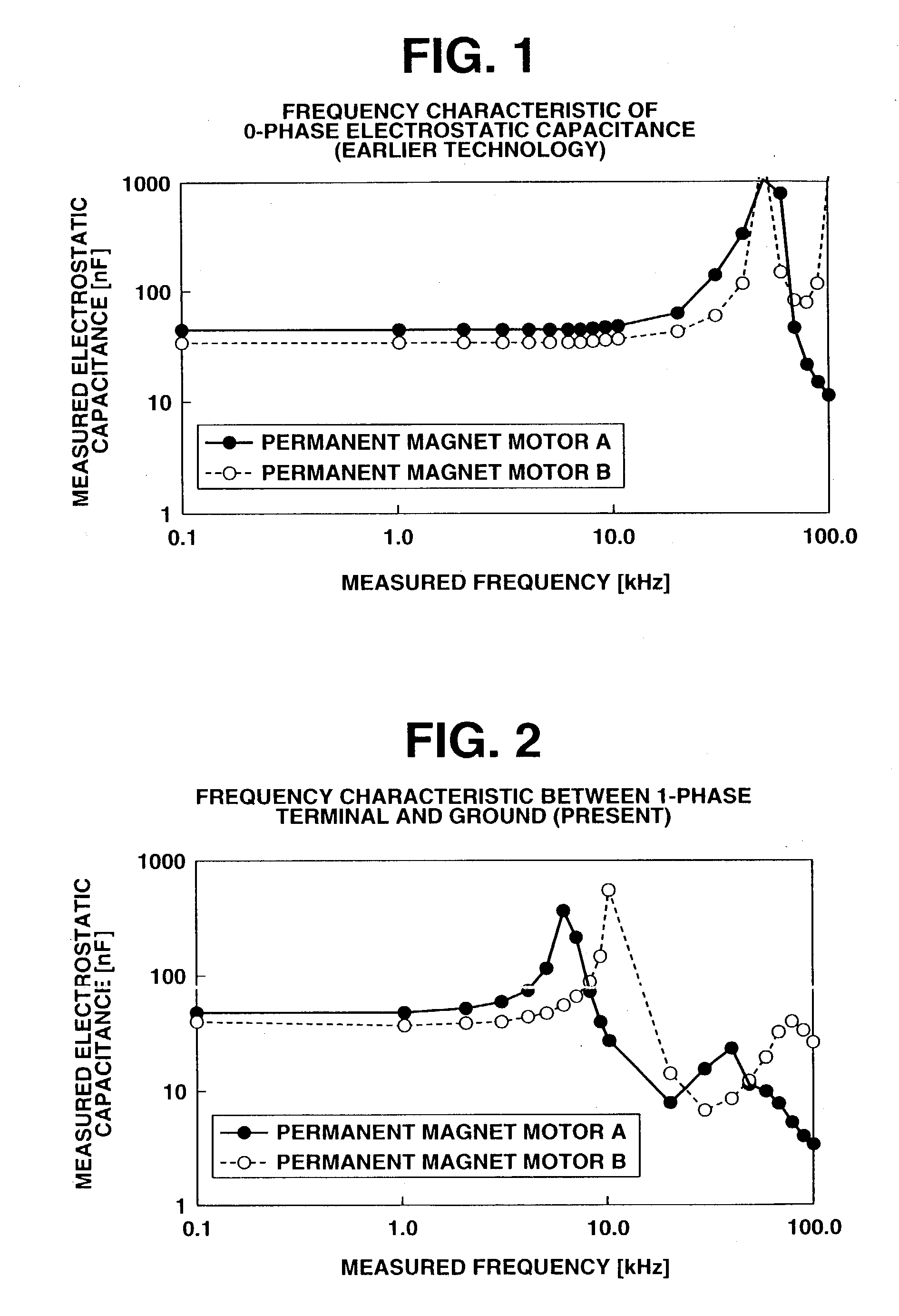
[0024] It is an object of the present invention to provide a permanent magnet synchronous motor driving system having a permanent magnet synchronous motor that can reduce a leakage current by preventing a resonant frequency (causing a peak electrostatic capacitance of the permanent magnet synchronous motor [in other words, referred to as "PM motor"]) from conforming with a carrier frequency (switching frequency) of an inverter. Hereinabove, the resonant frequency is generated between an inductance and a ground electrostatic capacitance of the permanent magnet synchronous motor.
[0025] It is another object of the present invention to provide a method of testing the permanent magnet synchronous motor driving system.

Problems solved by technology

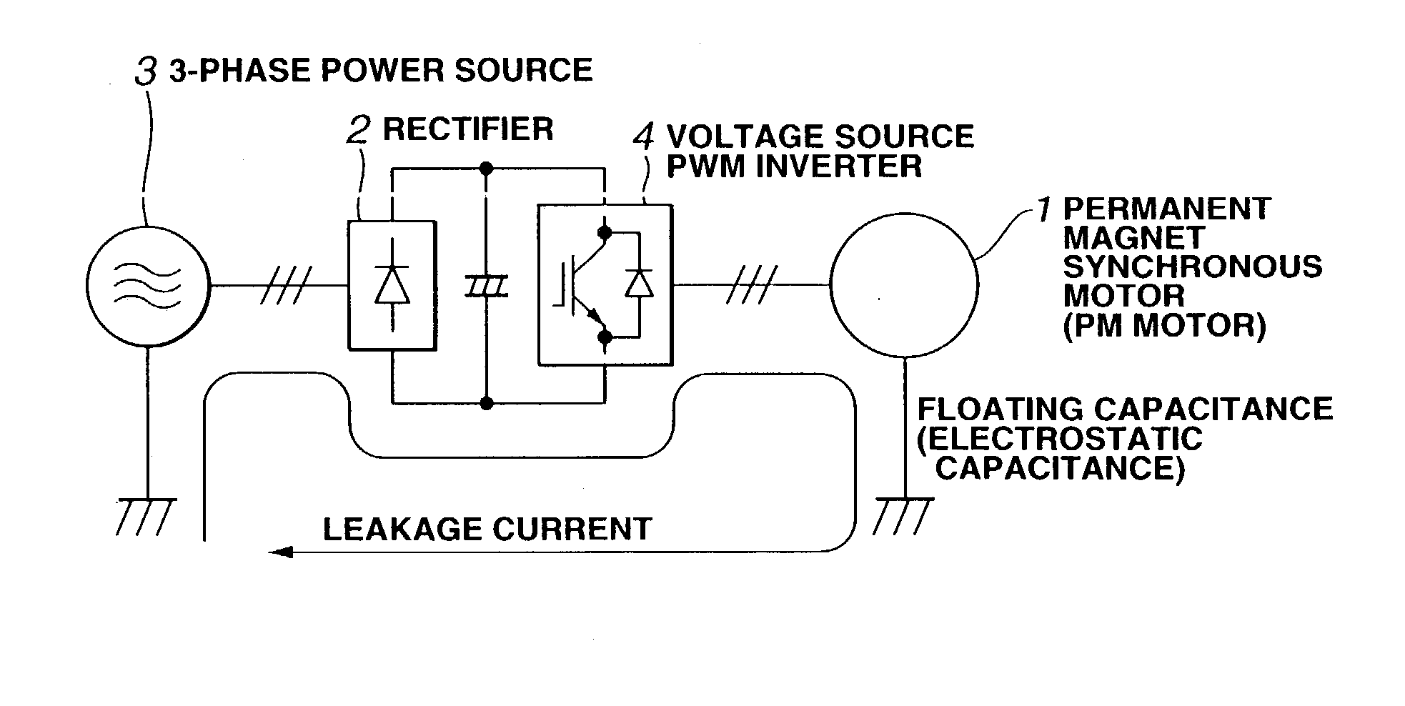
Adopting the 2-layer lap winding into the PM motor for the gearless hoist is likely to further increase the slot number Q. With this, a floating capacitance (electrostatic capacitance) between a winding terminal and ground is likely to increase, thus causing a leakage current with ease.
Especially, variably driving the PM motor by means of an inverter is likely to cause the leakage current having high frequency.
Hereinafter described is why variably driving the PM motor by means of the inverter is likely to cause the leakage current.
It has been proved, however, that taking only the zero-phase impedance into account cannot reduce the leakage currently effectively.
However, the carrier frequency of the PWM inverter conforming with the resonant frequency may greatly increase the electrostatic capacitance, thus increasing the leakage current.
In sum, taking only the zero-phase impedance (namely impedance having component of zero-phase) into account according to the earlier technology is not sufficient for effectively reducing the leakage current.
Especially, the PM motor for the gearless hoist is, in general, low in speed and low in frequency, thereby becoming great in the number of windings and thereby increasing impedance.

Method used


Image

  • Permanent magnet synchronous motor driving system, and method of testing permanent magnet synchronous motor driving system
  • Permanent magnet synchronous motor driving system, and method of testing permanent magnet synchronous motor driving system
  • Permanent magnet synchronous motor driving system, and method of testing permanent magnet synchronous motor driving system

Examples


Embodiment Construction

[0052] In the following, various embodiments of the present invention will be described in detail with reference to the accompanying drawings.

[0053]

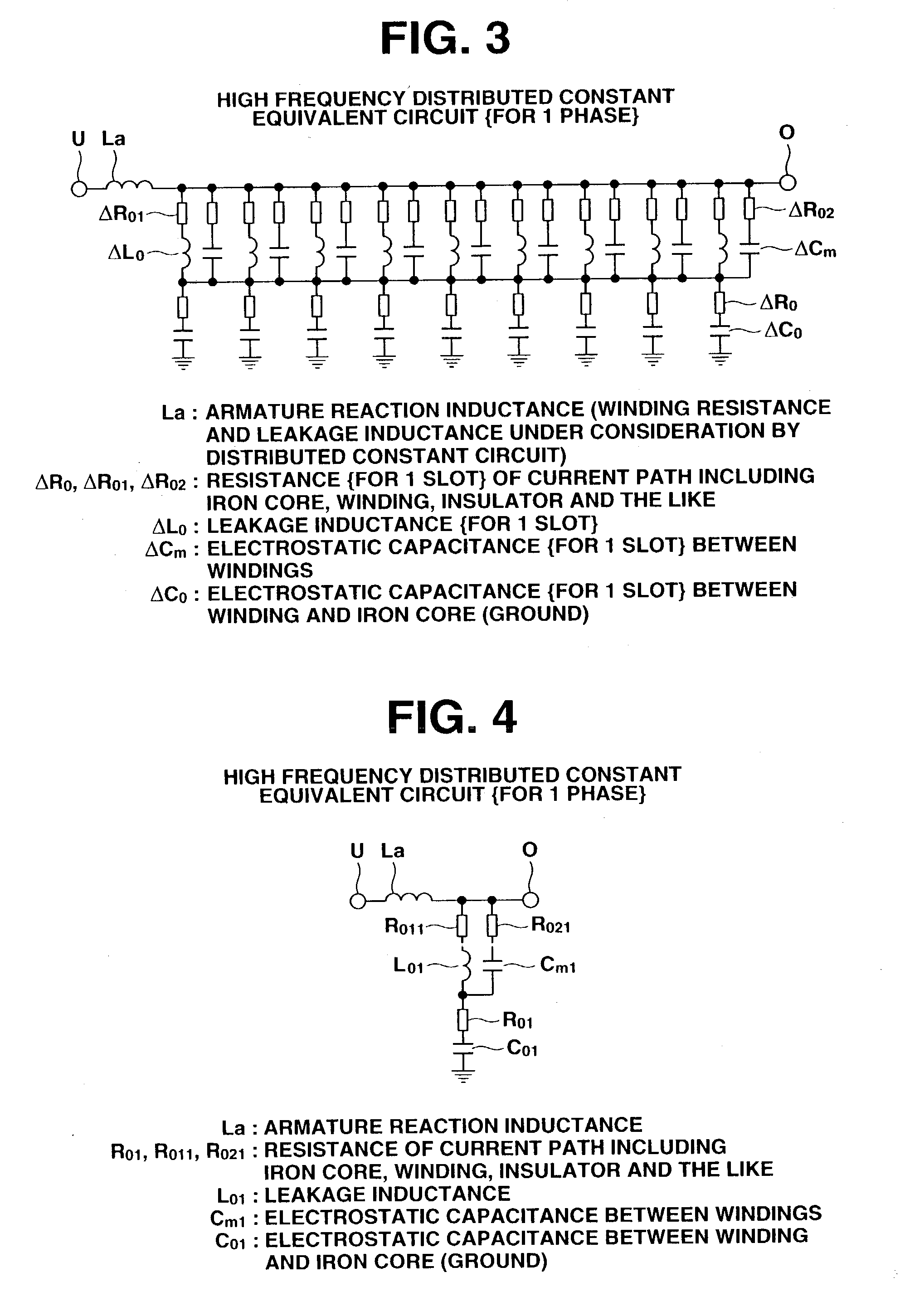
[0054] Various kinds of studies have been done on a leakage current from a motor driven by a PWM inverter. What is used for the studies is a distributed constant circuit. The distributed constant circuit is complicated, thus leaving no unified method or clarified literature. This describes a simple equivalent circuit and a simple method of determining the constant, for calculating the following elements:

[0055] 1. Low frequency ground electrostatic capacitance which is of importance for designing the motor.

[0056] 2. Frequency causing increased electrostatic capacitance (resonant frequency).

[0057] (1) High Frequency Equivalent Circuit

[0058] FIG. 3 shows a high frequency distributed constant equivalent circuit of a permanent magnet synchronous motor (hereinafter referred to as "PM motor" if necessary for convenience sake). The high freque...


PUM


Abstract

A permanent magnet synchronous motor driving system includes: 1) a permanent magnet synchronous motor, and 2) an inverter. The permanent magnet synchronous motor includes three phase terminals. A resonant frequency is generated between an inductance and a ground electrostatic capacitance which are measured between the following: a) one of the three phase terminals of the permanent magnet synchronous motor, and b) a ground. The inverter drives the permanent magnet synchronous motor. The inverter generates a carrier frequency. The resonant frequency of the permanent magnet synchronous motor is free from a conformance with the carrier frequency of the inverter and is free from a proximity of the carrier frequency of the inverter.

Description

[0001] 1. Field of the Invention[0002] The present invention relates to a permanent magnet synchronous motor driving system, and a method of testing the permanent magnet synchronous motor driving system.[0003] More specifically, the permanent magnet synchronous motor under the present invention is so devised as to have its leakage current reduced.[0004] The permanent magnet synchronous motor under the present invention is effectively used for an elevator.[0005] 2. Description of the Related Art[0006] In general, a permanent magnet synchronous motor (hereinafter referred to as "PM motor" if necessary for convenience sake) has a winding of 2-layer lap type (conventionally used). The PM motor for an elevator is supposed to have an inductive voltage waveform shaped substantially into sinusoid (sine curve) and to reduce torque ripple. Therefore, slot number Q (the number of slots) is, in general, likely to be maximized per pole and per phase.[0007] The PM motor for a gearless hoist has l...

Claims


Application Information

Patent Timeline
IPC IPC(8): B66B1/30B66B5/02H02K21/14H02K21/22H02P21/05H02P23/04H02P23/24H02P27/06H02P29/00
CPCY10S388/903H02P6/001H02P6/34H02M7/537
Inventor MIZUNO, TAKAYUKITAKAYAMA, JUNICHIHIGASHI, YOSHITAKA
Owner MEIDENSHA ELECTRIC MFG CO LTD
Learn More