
Method and apparatus for vaporizing fuel

a technology of vaporizing fuel and fuel injection, which is applied in the direction of mechanical equipment, combustion air/fuel air treatment, machines/engines, etc., can solve the problems of wasting 60% or more of the liquid fuel entering the combustion chamber, and reducing the efficiency of the internal combustion engine. , to achieve the effect of improving fuel economy, increasing the proportion of fuel supplied, and increasing the proportion of fuel in the combustion

Inactive Publication Date: 2003-07-31
PENTEL RANDOLPH M
View PDF13 Cites 9 Cited by
  • Summary
  • Abstract
  • Description
  • Claims
  • Application Information

AI Technical Summary

Benefits of technology

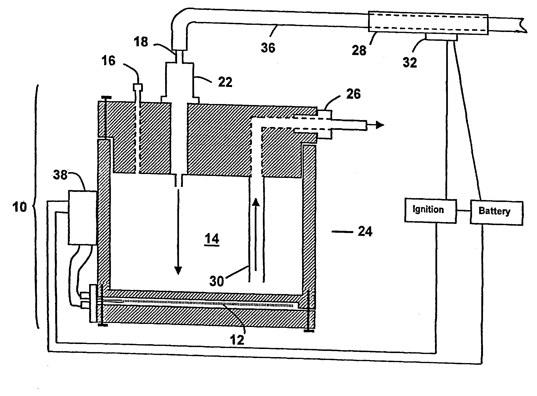
0018] The fuel vaporizer of the present invention is interposed between an internal combustion engine's fuel injection system and intake manifold. It functions to vaporize a substantial portion of the liquid fuel injected into it by the fuel injector, thereby dramatically increasing the proportion of fuel supplied to the combustion chambers of the engine as a gas rather than liquid. Since it is only in its gaseous form that the fuel is combusted, increasing the proportion of fuel in the combustion chamber as gas greatly increases the proportion combusted during the compression portion of an engine's cycle. The invention thus achieves a substantial improvement in fuel economy with a coincident reduction in pollutants through nearly complete combustion of the fuel. The invention will thus achieve enormous energy savings with fuel-injected engines of all kinds (both old and new) by an elegantly simple, safe and efficient means.

Problems solved by technology

Unfortunately, the internal combustion engine currently accomplishes this task inefficiently by the partial vacuum created in the combustion chamber (or cylinder) during the intake portion of an engine's cycle.
Unfortunately, less than 40% of the liquid fuel is typically vaporized in this process and combusted to provide power and heat.
Some 60% or more of the liquid fuel entering the combustion chamber is, therefore, wasted and exhausted to the environment.
They each fail to achieve this goal adequately, however, for reasons noted below.
This device provides no precise fuel control and may produce more fuel vapor than needed at low speeds and not enough at higher speeds.
The device provides no idle control and no way to move the vehicle until the device heats the fuel to its vapor point.
The device also may be hazardous in that it contains glow plugs that could potentially heat some of the fuel to its flash point and cause a fire.
This device contains design flaws, one involving the location of a float relative to nozzles that will result in little to no fuel flow in the device, and another that will result in a buildup of fuel at the device's atomizer.
Such a buildup of fuel could pose an explosion hazard if the vehicle is involved in an accident.
The main flaw in this device is its lack of a fuel flow control so that fuel flow can be regulated to match the vehicle's speed.
The device also could result in a buildup of fuel that would pose a danger of explosion in an accident.
The heating element of the device, however, does not heat the fuel sufficiently for vaporization.
This device fails to incorporate a means by which fuel flow can be regulated to match the requirements of the engine at variable speeds.
The heating wire of this device will not provide enough heat to vaporize the fuel and will potentially short out.
The fuel vapor that is formed in this device is not transported to the engine quickly enough to be responsive to changes in acceleration.
This device's heat source will not heat the fuel adequately to vaporize it.

Method used


Image

  • Method and apparatus for vaporizing fuel
  • Method and apparatus for vaporizing fuel
  • Method and apparatus for vaporizing fuel

Examples


Embodiment Construction

[0033] Referring now specifically to the figures, in which identical or similar parts are designated by the same reference numerals throughout, the first referring to FIG. 1, the components of the apparatus of one embodiment of the present invention are depicted and described. It should be understood that the following detailed descriptions relate to various of the currently known embodiments of the present invention. However, the present invention can assume numerous other embodiments, as will become apparent to those skilled in the art.

[0034] Embodiments--Apparatus

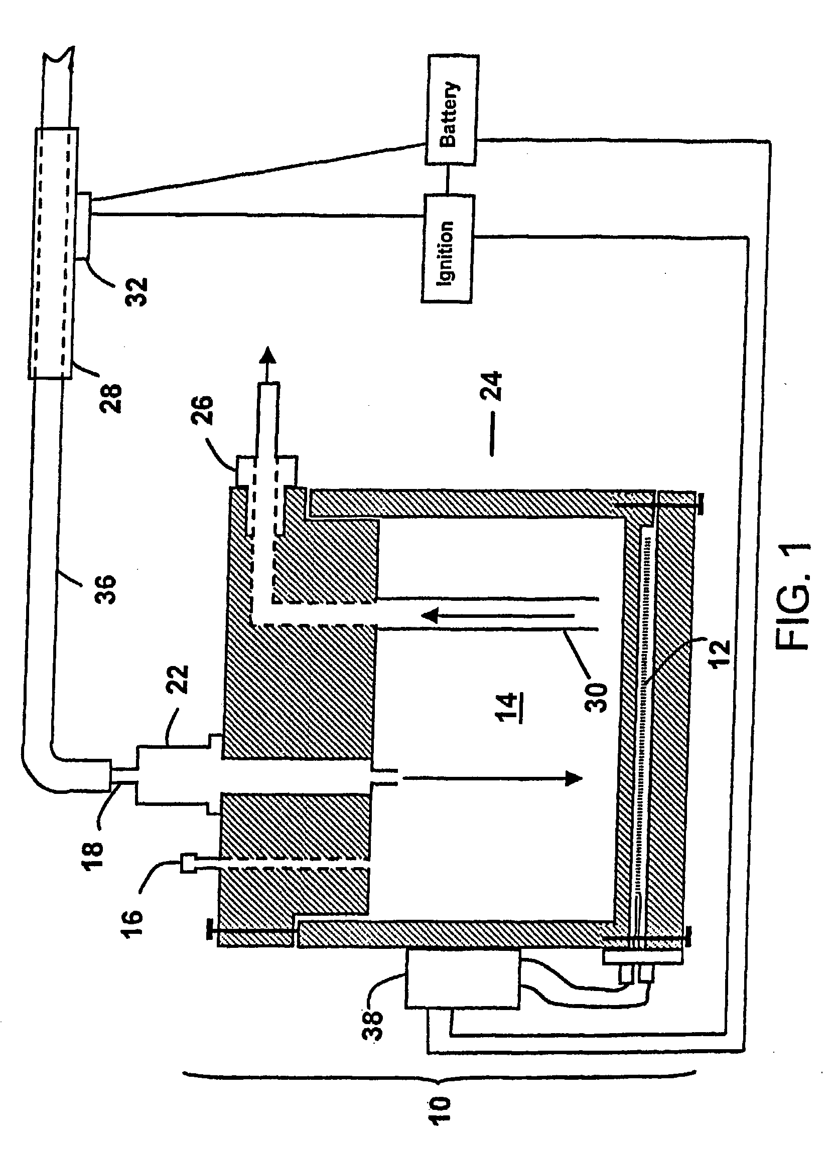
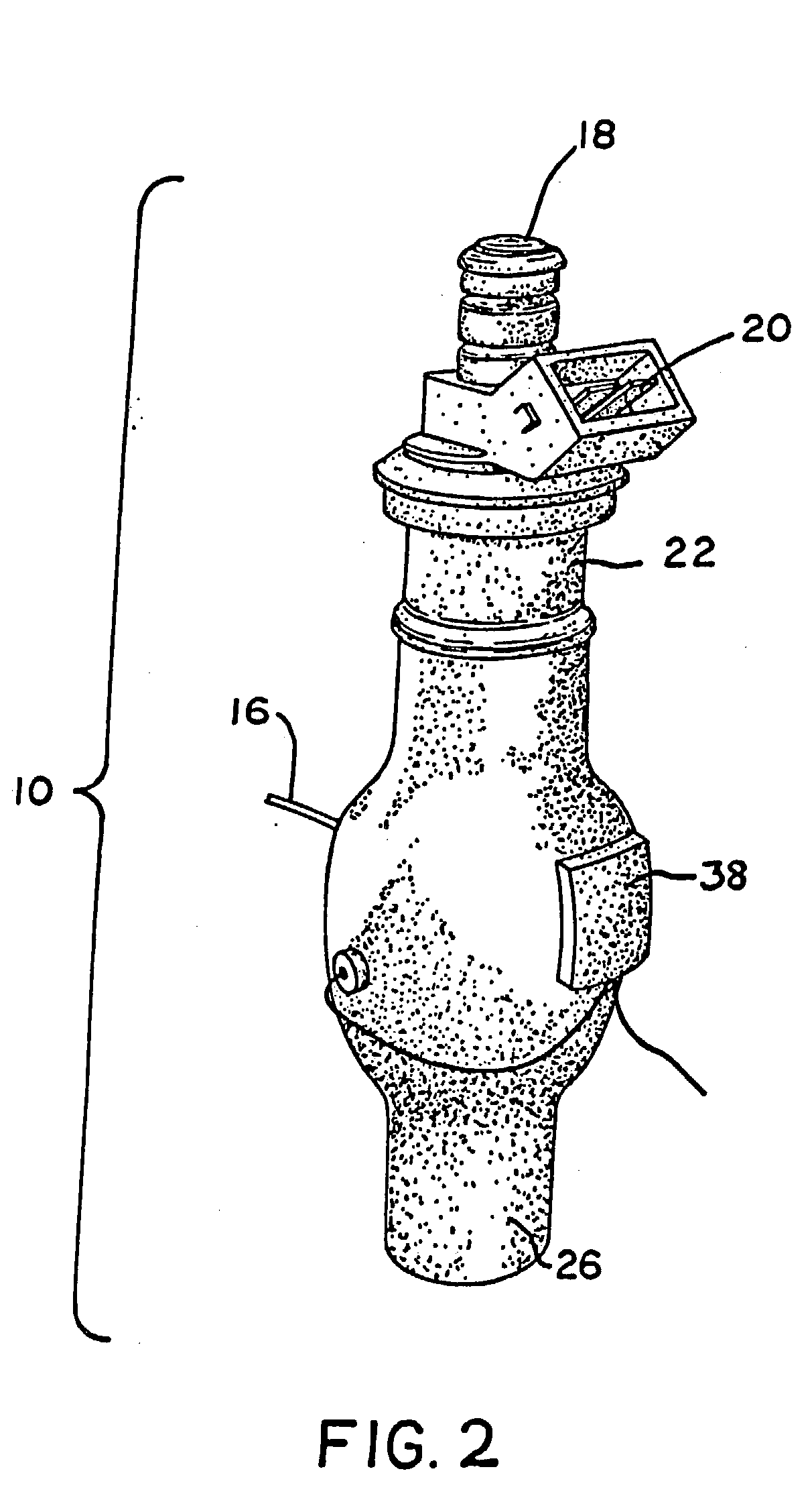
[0035] Referring to FIG. 1, the basic components of one embodiment of the present invention, a fuel vaporizer 10, are depicted. FIG. 1 is a cross-sectional view of a fuel vaporizer 10 in its more generic configuration for purposes of depicting its internal components. In this embodiment, the fuel vaporizer 10 is adapted for use in a fuel-injected internal combustion engine and is interposed between the engine's fuel inje...


PUM


Abstract

A method and apparatus is provided for the vaporization of liquid hydrocarbon fuel in a closed system prior to its entry into an internal combustion engine's combustion chambers in amounts proportional to the acceleration level of the engine. The apparatus is a fuel vaporizer interposed between an engine's fuel injection system and combustion chambers and forms a canister housing. Liquid fuel enters via an inlet in the housing, is vaporized by heating it to boiling and is drawn out of the canister via an outlet under a partial vacuum to the combustion chambers of the engine. The system is closed except for a vacuum connection with the engine's combustion chambers. Heating means are provided to heat the fuel to boiling without heating it to its flash point, thus avoiding its pre-ignition.

Description

[0001] This is a continuation-in-part of Ser. No. 09 / 674,863 filed Nov. 7, 2000 which was entitled to the benefit of U.S. Provisional Patent Application Serial No. 60 / 150,421, filed Aug. 24, 1999 and is a U.S. National filing from International Application PCT / US00 / 22999. Applicant requests that Disclosure Document no. 458891, filed at U.S. Patent and Trademark Office on Jul. 10, 1999, be associated with this application.[0002] The present invention is directed to fuel vaporizer devices for vaporizing liquid fuel supplied to an internal combustion engine, and more specifically to a method and apparatus for efficiently vaporizing liquid hydrocarbon fuel in a closed system prior to its entry into an internal combustion engine's combustion chambers in amounts proportional to the acceleration level of the engine, thereby increasing the engine's fuel efficiency and decreasing the engine's emissions of pollutants to the environment.[0003] In an internal combustion engine, combustion of a ...

Claims


Application Information

Patent Timeline
Patent Type & Authority Applications(United States)
IPC IPC(8): F02M31/18
CPCY02T10/126F02M31/18Y02T10/12
Inventor NEWHOUSE, LESLIE A.PENTEL, RANDOLPH M.
Owner PENTEL RANDOLPH M
Learn More