Process for treating wastes from acrylic acid and polyacrylic acid production processes

a technology of polyacrylic acid and waste, which is applied in the direction of separation process, combustion type, treatment water nature, etc., can solve the problems of clogging of combustion furnace and heat exchanger, high combustion cost,

Inactive Publication Date: 2003-07-31
NIPPON SHOKUBAI CO LTD
View PDF13 Cites 9 Cited by
  • Summary
  • Abstract
  • Description
  • Claims
  • Application Information

AI Technical Summary

Problems solved by technology

The water-absorbent resin waste waters, being hardly combustible, have required an additional combustion aid for combustion thereof, resulting in a higher combustion cost.
When only the acrylic acid waste gases are burned, the waste gases, having a high concentration of organic matters and the like, sometimes cause problems of clogging in the combustion furnace and the heat exchangers due to adhesion of organic matters and the like.

Method used


Image

  • Process for treating wastes from acrylic acid and polyacrylic acid production processes
  • Process for treating wastes from acrylic acid and polyacrylic acid production processes

Examples


example 1

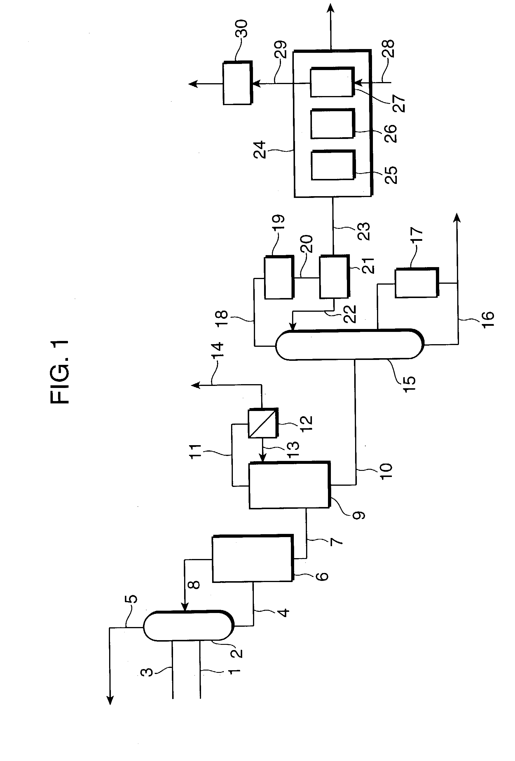
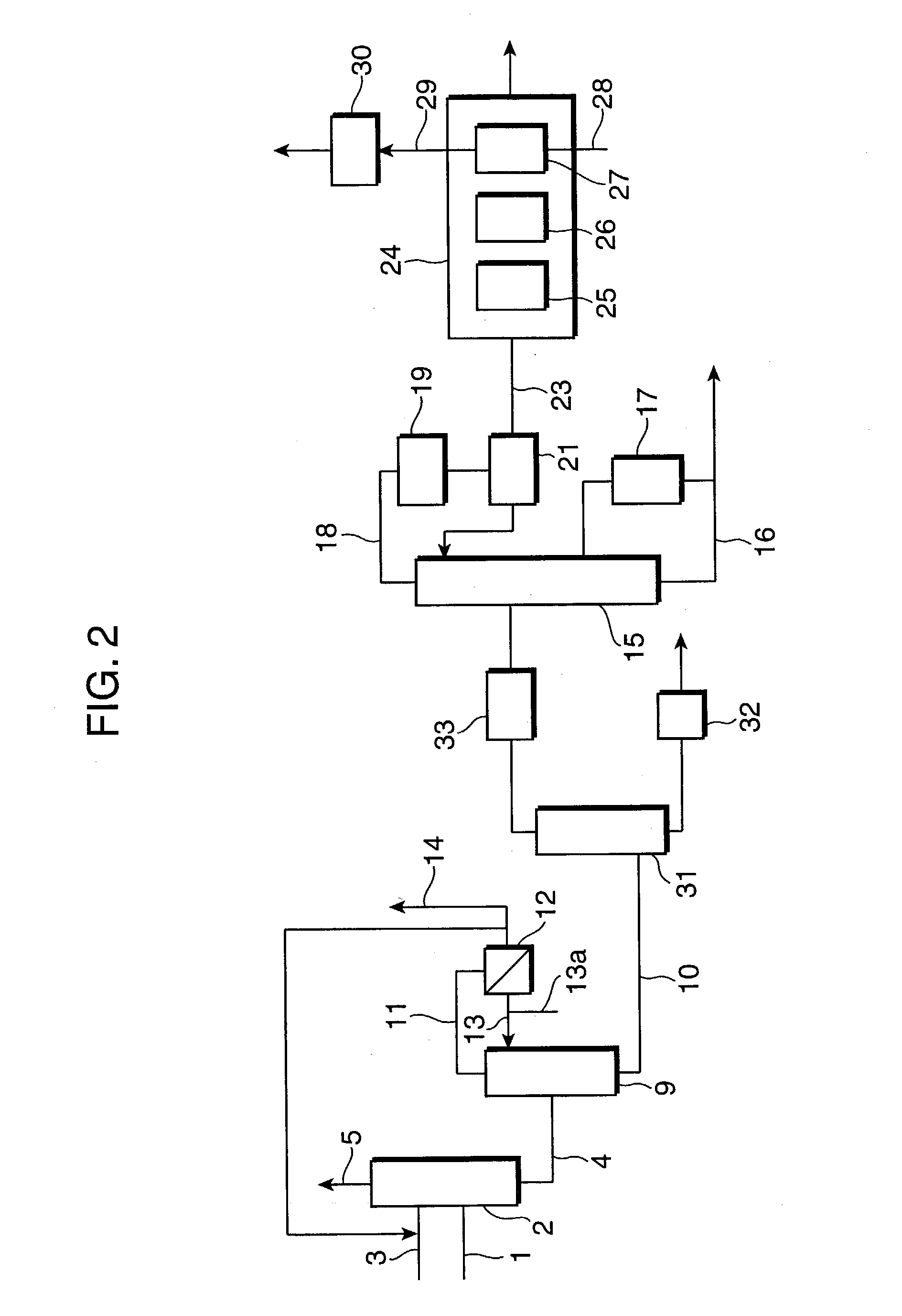
[0051] A gas containing acrylic acid obtained by gas-phase oxidation of raw gases containing propylene was fed via line 1 into absorption column 2, and distilled water from distillation column 9 was fed as an absorption solvent via line 3 into the same absorption column, to give an acrylic acid solution. The acrylic acid solution was supplied to azeotropic distillation column 9 and an azeotropic solvent was fed via line 13a into the azeotropic distillation column. Low boiling impurities containing water are separated as the distillate from the top of the column. The distillate was fed into an apparatus for separating azeotropic solvents (decanter) 12, and after oil / water separation, a part of the aqueous phase was recycled to absorption column 2, and the other part was discharged (1.7 m3 / h) via line 14 as a waste water (hereinafter, referred to as "waste water A"). Meanwhile, the waste water A had a composition of 1.8 mass % of acrylic acid, 5.7 mass % of acetic acid, and the balanc...

example 2

[0053] The waste gas (containing 1000 vol. ppm of acrylic acid and 19.8 vol. % of water) discharged (555 Nm.sup.3 / min) from the top of the absorption column in the acrylic acid production process described in EXAMPLE 1 above, and the hot waste gas (containing 30 vol. ppm of acrylic acid and 19.8 vol. % of water) discharged (300 Nm.sup.3 / min) from the water-absorbent resin production process were preheated in a plate heat exchanger and supplied to and burned in a catalytic combustion apparatus. After a month of operation, there was no deposit in the heat exchanger found upon inspection.

example 3

[0054] The waste gas (containing 1000 vol. ppm acrylic acid and 19.8 vol. % of water) discharged (555 Nm.sup.3 / min) from the top of the absorption column in the acrylic acid production process described in EXAMPLE 1, the waste water A discharged (1.7 m.sup.3 / h) after oil / water separation of the distillate form the top of the azeotropic distillation column, and the hot waste gas (containing 30 vol. ppm of acrylic acid and 19.8 vol. % of water) discharged (300 Nm.sup.3 / min) from the water-absorbent resin production process are supplied to an combustion furnace. The waste gas, the waste water A, and the hot waste gas above are fed and burned in the combustion furnace that is separately supplied with natural gas to maintained the internal temperature at 900.degree. C., giving a purified non-hazardous gas to be released outside.


PUM

PropertyMeasurementUnit
temperatureaaaaaaaaaa
mass %aaaaaaaaaa

Abstract

Disclosed is a process for treating wastes discharged from an acrylic acid production process and a consecutive polyacrylic acid production process in which at least one waste selected from the group consisting of waste oil, waste water, and waste gas from said acrylic acid production process, and waste water and/or waste gas from said polyacrylic acid production process are combusted simultaneously.

Description

[0001] 1. Field of the Invention[0002] The present invention relates to a process for treating by-products from an acrylic acid production process, and a consequent process such as polyacrylic acid production process wherein the same acrylic acid is used as a raw material. In particular, it relates to a process to treat efficiently waste gases, oils and waters discharged from a production process of high purity acrylic acid composed of a variety of steps such as reaction, separation, purification, etc., and waste gases and waters from a production process for polyacrylic acids such as water-absorbent resins.[0003] 2. Description of the Prior Art[0004] Acrylic acid has been produced in a variety of processes. These processes are composed of a variety of steps such as reaction, separation and purification in the course of conversion from raw materials finally into high purity acrylic acid. By-products and impurities separated and removed from each of the steps are discharged as waste ...

Claims


Application Information

Patent Timeline
Patent Type & Authority Applications(United States)
IPC IPC(8): B01D53/38B01D53/72C02F1/72C07B35/06C07B37/06C07C57/04F23G5/00F23G7/00F23G7/04F23G7/05F23G7/06
CPCB01D53/38B01D53/72B01D2257/702C02F1/72F23G7/065C02F2103/38F23G5/006F23G7/001F23G7/05C02F2103/36
Inventor MATSUMOTO, YUKIHIRONAKAHARA, SEIISHIZAKI, KUNIHIKO
Owner NIPPON SHOKUBAI CO LTD
Why Eureka
Try Eureka