Plastic pipe adhesive joint

a technology of adhesive joints and plastic pipes, which is applied in the direction of hose connections, screw threaded joints, mechanical equipment, etc., can solve the problems of deteriorating cabling protected by conduits, loss of products, and continuous leakage of pipes in such systems

Inactive Publication Date: 2003-08-21
HOLLINGSWORTH ELMONT E +1
View PDF23 Cites 29 Cited by
  • Summary
  • Abstract
  • Description
  • Claims
  • Application Information

AI Technical Summary

Benefits of technology

[0017] The foregoing objects are achieved in a method of joining two pipe ends, generally comprising the steps of forming a plurality of male threads on an end of a first pipe member, wherein the male threads have a steep taper angle, forming a plurality of female threads on an end of a second pipe member, wherein the female threads have the steep taper angle and are adapted to engage the male threads, applying adhesive material to a selected one of the male and female threads, aligning male threads with the female threads as the end of the first pipe member is brought into contact with the end of the second pipe member, then twisting the pipe members to fully engage the male and female threads, and thereby spread the adhesive material across adjacent load-bearing surfaces of the threads. Thereafter, the adhesive material is allowed to cure. The invention is particularly suited for use with polymeric pipe, and the threads can either be molded into the pipe ends, cut using a computer-controlled lathe or cut with other specialty thread cutting machines. The threads have multiple start locations for thread engagement. The pipe ends may be twisted to achieve full engagement in less than one full relative rotation of the pipes. The freshly assembled joint thereby formed provides immediate low pressure leak-tightness and immediate tensile, compressive and torsional strength. The curing of the adhesive results in improved strength and sealing.

Problems solved by technology

There is a continual problem regarding leakage in such pipe systems due to inadequate joining of pipe sections.
Leakage may be from the inside of the pipe to the outside (e.g., water or natural gas) resulting in the loss of product, or from the outside of the pipe to the inside (e.g., water penetration) which may deteriorate cabling that is protected by the conduit.
Joining pipe using adhesives, however, is generally unacceptable due to the difficult adherence characteristics of many polymers, which can result (after a period of time) in cracks in the cured adhesive or in separation of the adhesive from the pipe surface.
The use of adhesive or glue (which may be toxic) also often involves a change in the inner diameter or outer diameter of one or both of the pipes, such as with a bell-and-pipe slip joint.
Non-uniform pipe diameters can introduce difficulties when installing the pipe.
Solvent-based joining materials do not achieve any level of bond strength on polyethylene and other low-surface energy piping materials.
As with other prior art techniques, however, electrofusion couplers often do not create a complete seal and the entire process must sometimes be repeated.
Electrofusion couplers are also relatively expensive.
This system is very complicated, however, as it requires a special microwave cavity and power supply, both of which can be very bulky.
This technique also presents safety hazard to workers who may be exposed to microwave radiation.
While threading is an acceptable way of joining certain kinds of pipe, particularly metal pipe, it is again much less useful in joining plastic pipe.
Plastic threads do not have the strength of metal threads, and are more susceptible to stripping.
Also, when a straight thread is used to connect two cylinders, a deep shoulder is required to accommodate each thread (male and female), which accordingly decreases the longitudinal strength of the cylinder wall.
To avoid this problem, it is necessary to alter either the inner diameter or outer diameter of one of the pipes, which may lead to the difficulties mentioned above.
This design, however, still does not provide a sufficient mechanical connection or a reliable high pressure seal.

Method used


Image

  • Plastic pipe adhesive joint
  • Plastic pipe adhesive joint
  • Plastic pipe adhesive joint

Examples


Embodiment Construction

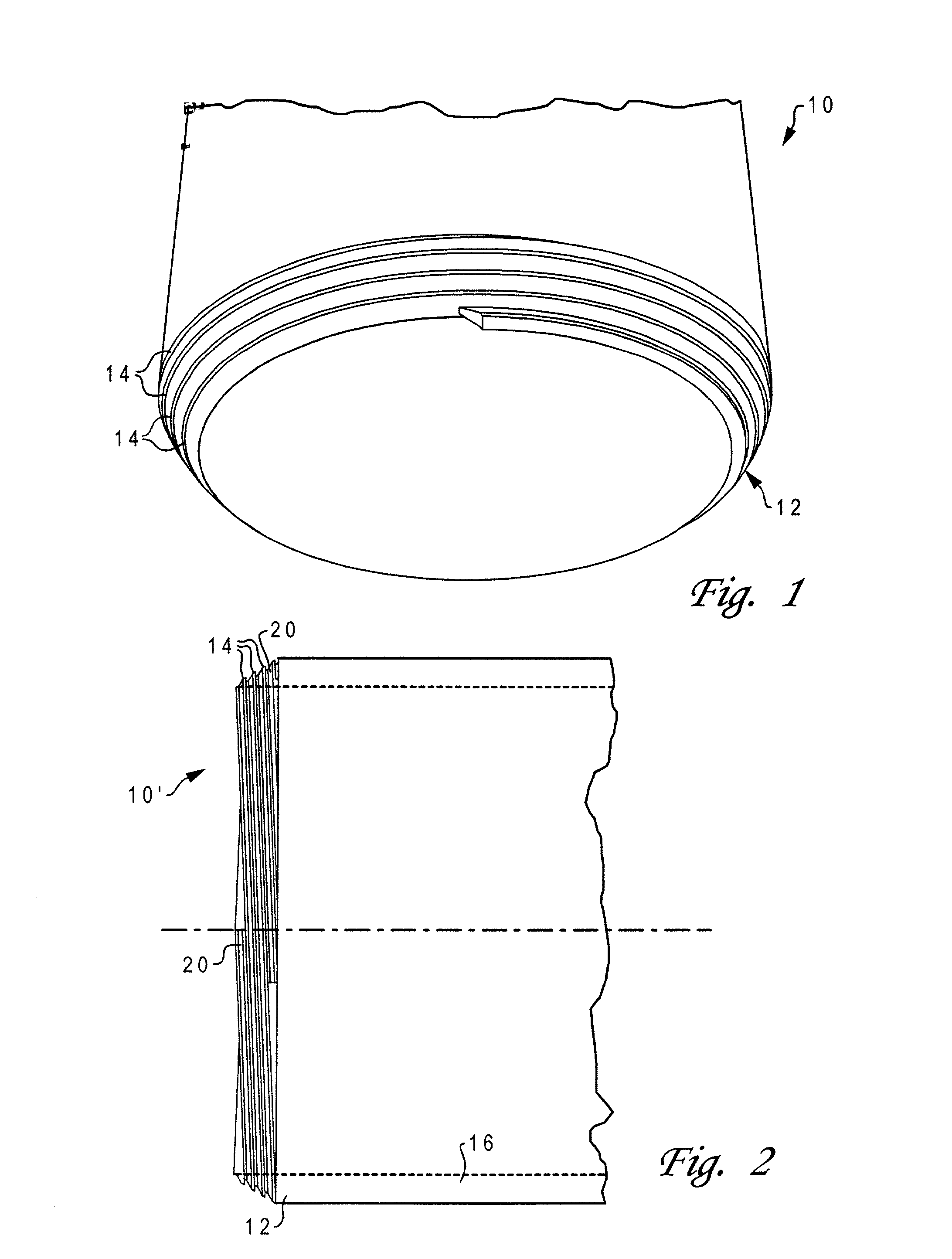
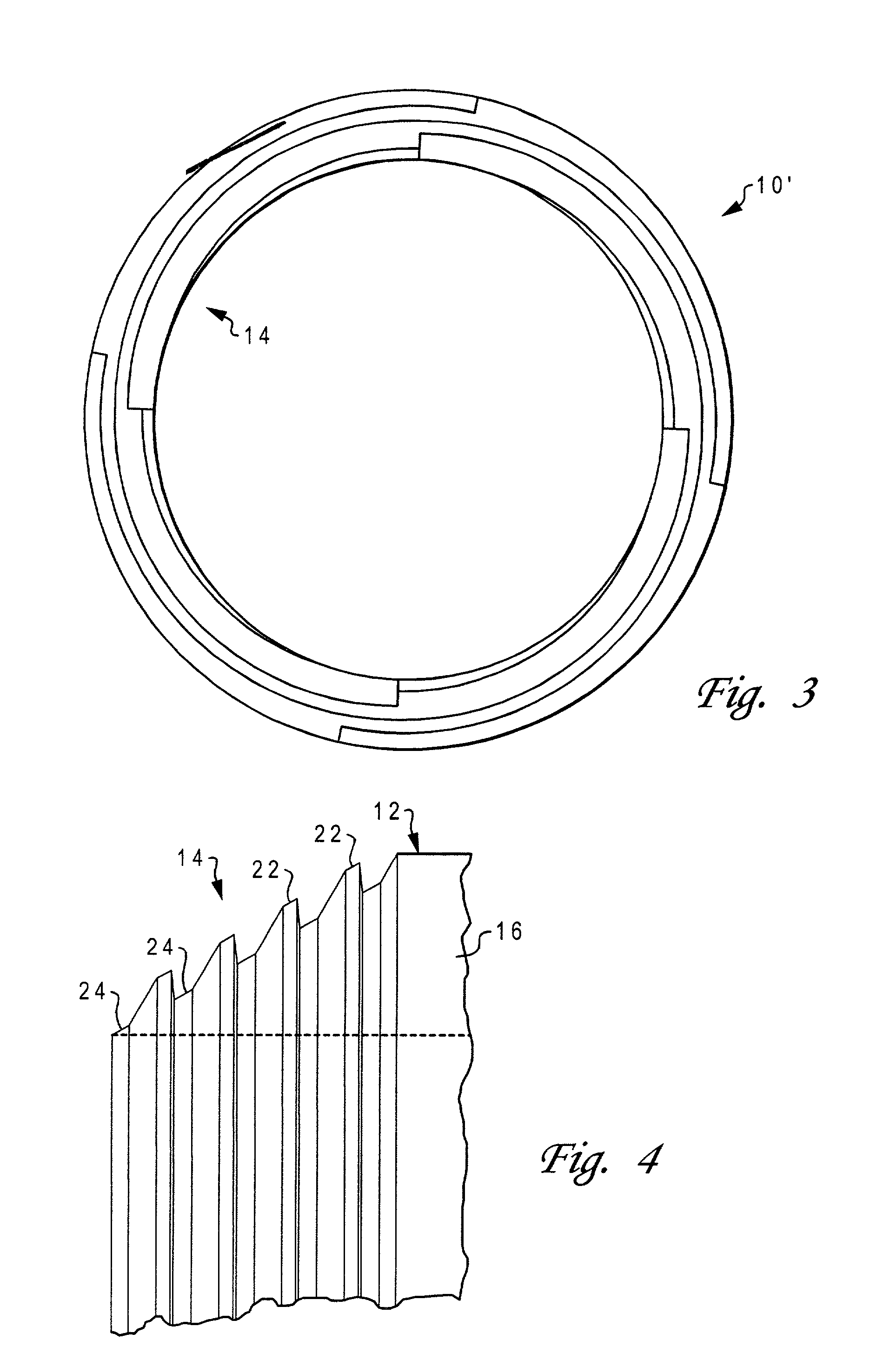
[0028] With reference now to the figures, and in particular with reference to FIG. 1, there is depicted one embodiment 10 of a pipe constructed in accordance with the present invention. Pipe 10 is cylindrical with a generally circular cross-section, and has an end 12 provided with male threading 14. The hollowed interior of the pipe may be used to convey a particular fluid product, or may accommodate other conduits e.g., telecommunications lines.

[0029] Pipe 10 may be constructed of any durable material, preferably a rigid polymer such as polyvinyl chloride (PVC) or acrylonitrile butadiene styrene (ABS). The specific dimensions of pipe 10 may vary considerably, depending upon the application. For example, the outer diameter of pipe 10 might be as small as half an inch, or as large as six feet. The length of pipe 10 may similarly vary, from a couple of feet to a hundred feet or more.

[0030] Threading 14 is tapered across the complete thickness of pipe wall 16. The taper angle is relati...


PUM

PropertyMeasurementUnit
squeeze angleaaaaaaaaaa
outer diameteraaaaaaaaaa

Abstract

A method of joining two pipe ends, by forming male threads on an end of a first pipe with a steep taper angle, forming matching female threads on an end of a second pipe, and applying adhesive material to the threads before twisting the pipes to fully engage the male and female threads, thereby spreading the adhesive material across adjacent load-bearing surfaces of the threads. The threads have multiple start locations for thread engagement so that the pipe ends may be twisted to achieve full engagement in less than one full relative rotation. The male and female threads are formed with a squeeze angle between matching surfaces of the threads between 0.5 and 5.0 degrees. The finished joint provides immediate leak-tightness, and immediate tensile, compressive and torsional strength and does not protrude outside of the pipe profile. The technique may also be used to join pipes constructed of dissimilar materials, particularly by using a coupler that has the appropriate threading, and securing the coupler to a non-threaded pipe end using any convenient means, such as a mechanical fit, or fusion bonding.

Description

[0001] This application claims priority to U.S. Provisional Application No. 60 / 358,664 filed on Feb. 21, 2002, and to Patent Cooperation Treaty Application No. PCT / US01 / 28697 having a priority date of Sep. 15, 2000, both of which are hereby incorporated in their entirety.[0002] 1. Technical Field[0003] The present invention generally relates to methods and systems used to attach structural members, more specifically, to a joint for connecting conduits, and particularly to a joint that may be used to provide both mechanical attachment and a complete pressure seal for polymeric (plastic) pipe.[0004] 2. Description of Related Art[0005] Many types of conduits are used to provide various utility services, such as telephone, cable, water, waste water, and natural gas. These conduits come in a variety of sizes, shapes and materials. One of the most common forms is a pipe having a circular cross-section, constructed of a polymeric (plastic) material, particularly acrylonitrile butadiene sty...

Claims


Application Information

Patent Timeline
Patent Type & Authority Applications(United States)
IPC IPC(8): F16L47/02F16L47/16
CPCF16L47/16F16L47/02
Inventor HOLLINGSWORTH, ELMONT E.MINAROVIC, JOE T.
Owner HOLLINGSWORTH ELMONT E
Why Eureka
Try Eureka