Advanced processes for coring and grouting masonry

a technology of coring and grouting and masonry, which is applied in the direction of turning machine accessories, drilling pipes, and drilling holes/wells, etc., can solve the problems of insufficient viscosity, insufficient liquidity insufficient strength of cementious grouting materials, etc., to achieve less accurate, less costly in drill-bit wear and replacement, and faster rate

Inactive Publication Date: 2003-09-11
MOHLENHOFF WILLIAM
View PDF0 Cites 30 Cited by
  • Summary
  • Abstract
  • Description
  • Claims
  • Application Information

AI Technical Summary

Problems solved by technology

Removal of cuttings is generally more difficult and critical.
There is a considerable quality-control problem with water-based and cementious materials in regard to this wetting requirement, especially as to uniform optimal wetting.
The stronger mixtures of cementious grouting materials also are not liquid enough; i.e., do not have low enough viscosity to fill all the small cracks and voids left by masons in the original construction.
Further, the water in water-based grouting materials is the solvent, but it does not carry the adhesive well into cracks and voids to form a network of bonding.
None of these Center-Cored buildings sustained even structural cracking in Center-Cored areas, while buildings around them cracked badly and structural failures with cracking and even partial collapses were common among masonry buildings in the same area.
A few were by concrete wet drilling companies who had many problems in schedule delays, cost overruns and job failures.
However, all masonry buildings in seismically hazardous areas should use the method.
A wide kerf bit disadvantage is that the drill column is free to wander more.
As the column becomes longer in deeper drilling, the torque required is greater and may tend to twist the column and cause it to wander off-center.
Hard materials and voids encountered in the masonry also cause drill misalignment.
However, in the present double-piped, triple passage patent, off-the-shelf hardware is not available to adapt to the method and, also, novel new hardware innovations are required to facilitate the new system features discussed below.

Method used


Image

  • Advanced processes for coring and grouting masonry
  • Advanced processes for coring and grouting masonry
  • Advanced processes for coring and grouting masonry

Examples


Embodiment Construction

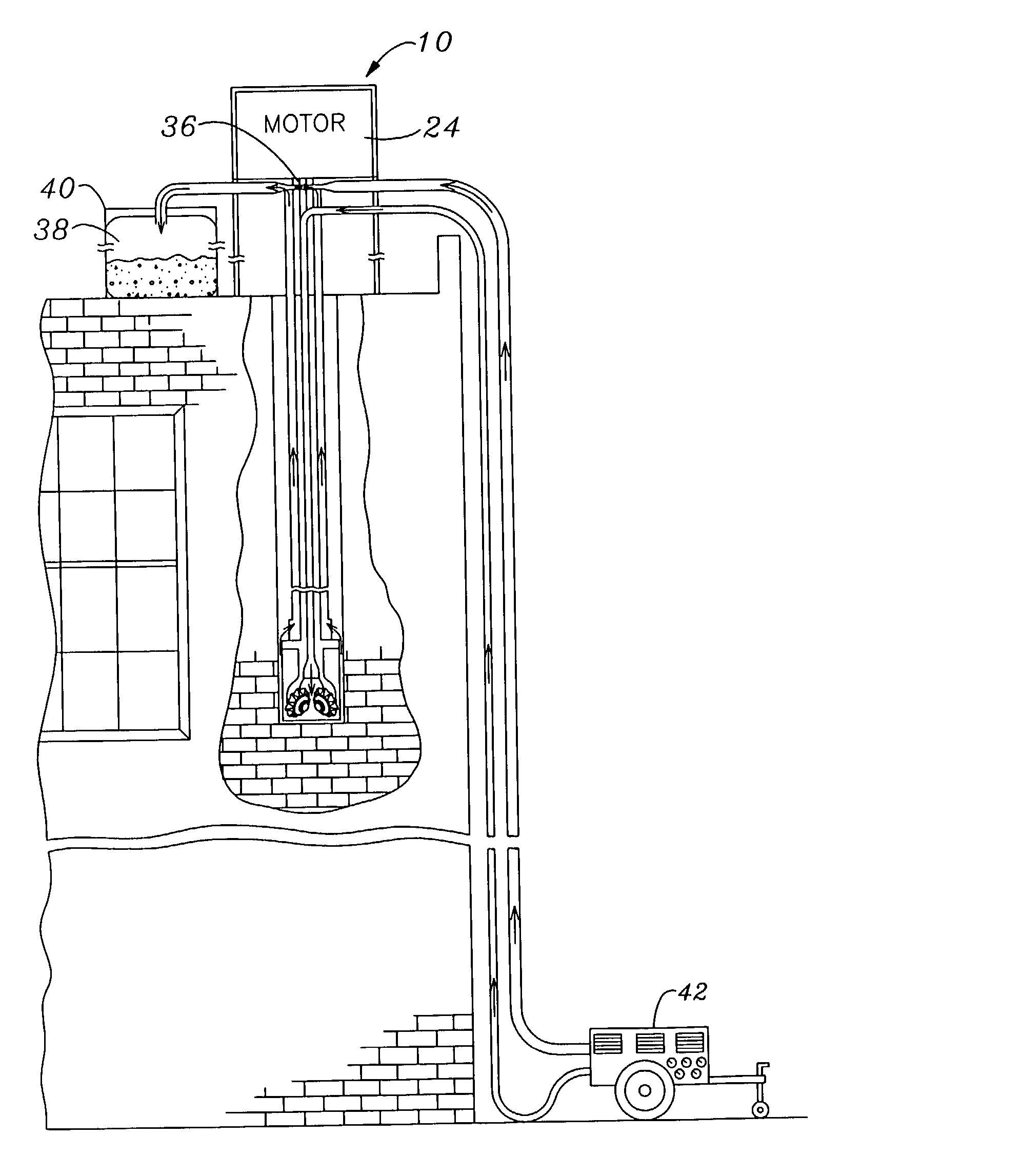
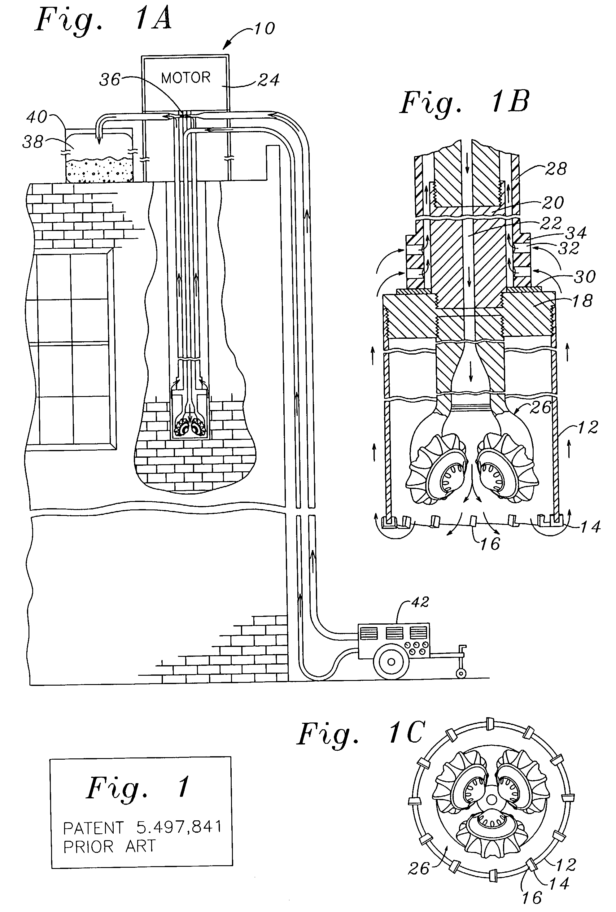
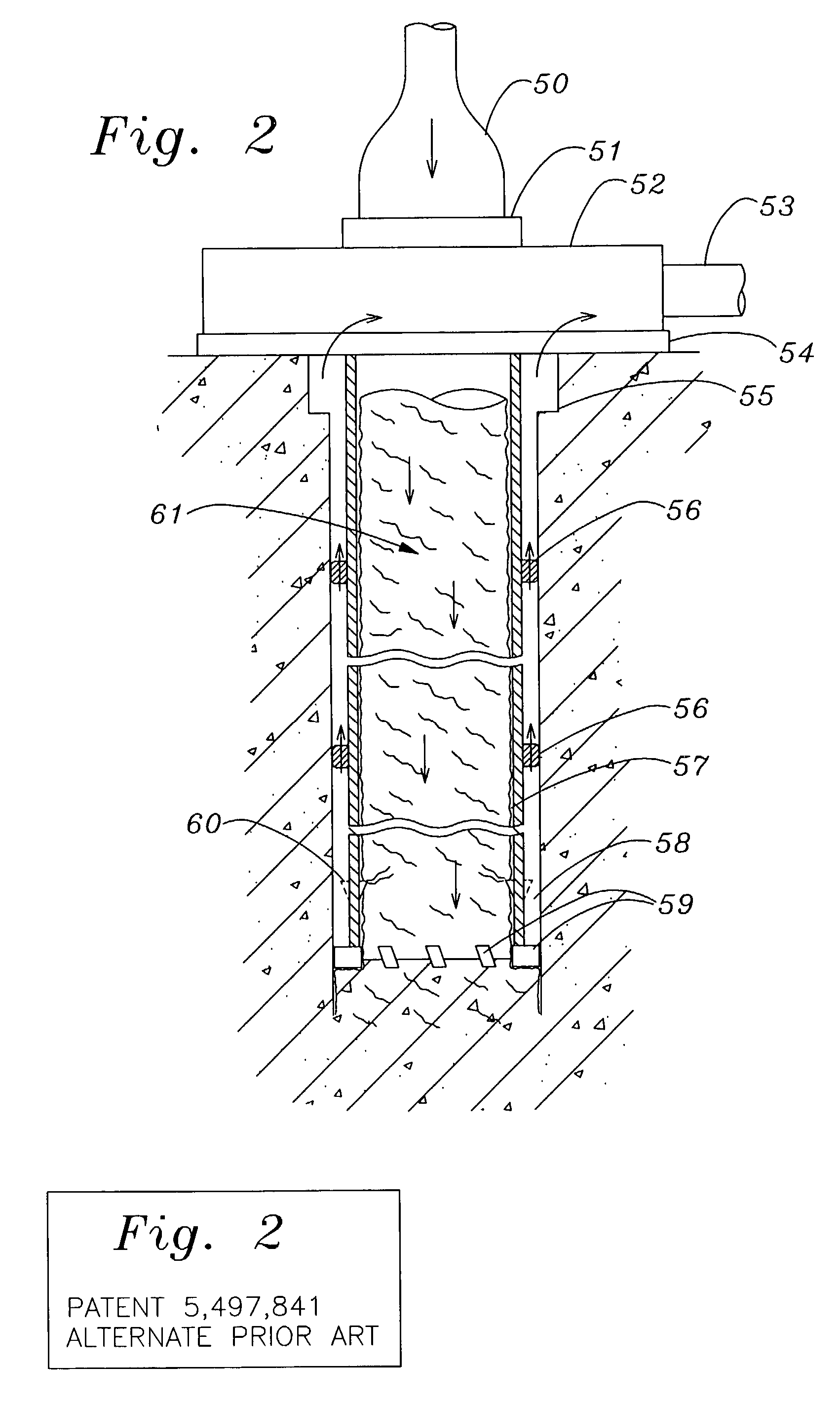
5,497,841 SECTIONS, THREADED UP OUTSIDE OF PIPE, Mostly Water-Cooled TO BE JOINED OR OUT THROUGH TOGETHER. HOLES IN WALL PATENT 5,497,841 (PRIOR ART) a. EXAMPLE GIVEN IN a. WITH FULL SINGLE-PIPE WITH PATENT 5,497,841. PULVERIZATION. AIR AUXILIARY CONCENTRIC SHAFT 1.75 in. dia.; DOWN HOLE IN SHAFT PIPE OUTSIDE DRILL CONCENTRIC PLASTIC AND AIR / DUST UP SHAFT, RIDING ON DRILL PIPE, RIDING ON DRILL BETWEEN SHAFT AND BODY. ALTERNATE SINGLE BODY; found NON-AUX PIPE RIDING ON PIPE & CORE CATCHER. OPTIMUM; or DRILL BODY; or A VENTURI VACUUM b. STRONG STEEL. b. WITH CORE CATCH-THIS IS THE NEXT STEP DRILL PIPE WITH CORE ER, AIR OR WA-UP IN COST FROM PRE- CATCHER; NO AUX TER / AIR MIST OR PATENT SYSTEM; PIPE; REAMERS FOAM IS ROUTED DOWN ALLOWS FULL USE OF PREVENT TORQUE THROUGH SOLID CORE AIR EXTRACTION, AVOID- TWIST FOR WIDE KERF INNER PASSAGE VOIDS ING USE OF WATER TO BIT LEAVING WIDE GAP AND UP PASSAGE PRESERVE BUILDING BETWEEN PIPE AND BETWEEN PIPE & CORE ARCHITECTURE. CORE WALL. WALL. NEW PA...


PUM

PropertyMeasurementUnit
depthaaaaaaaaaa
diameteraaaaaaaaaa
diameter sizesaaaaaaaaaa

Abstract

Advanced masonry coring systems for coring and grouting masonry walls are disclosed in this patent. The systems include rotating machinery and a drill column in the form of a cylindrical double-piped string of pipe sections, rotating a cylindrical drill body. The drill body mounts cutting end faces having alternative means of employing carbide or diamond cutting and / or pulverizing elements. The double drill pipe weight is made workable through new aerospace composite fabrication. The double pipe permits more efficient routing of air and removal of drill cuttings. Advancement in various system components and means of placing reinforcement into walls is disclosed. Further disclosure is included of advanced means of optimizing resin grouting materials and procedures to fill the wall cavities created by the core drill, integrating the reinforcement into the walls.

Description

[0001] 1. Field of the Invention[0002] This invention is addressed to the processes of structural retrofit of masonry buildings, including masonry of all types and degrees of hardness and consistency, from adobe or other earthen construction to the hard granites, basalts and concretes.[0003] 2. Description of Prior Art[0004] The optimization of the Air Extraction core-drilling system design for the processes of structural retrofit use is much different from that of well-drilling or geological systems for open drilling in ground or rock strata. Construction wet drilling of short cores in concrete had been developed from these sources. However, dry, or near-dry drilling of longer cores is essential in many structures and highly desirable in nearly all buildings needing reinforcement. Accuracy and wall protection are emphasized in construction structural applications. Cost is of paramount importance. Removal of cuttings is generally more difficult and critical. Encounters with steel ar...

Claims


Application Information

Patent Timeline
Patent Type & Authority Applications(United States)
IPC IPC(8): B28D1/04B28D1/14B28D7/02E04G23/02E21B17/18E21B21/12E21B25/10
CPCB28D1/041B28D1/14B28D7/02E04G23/0218Y10T408/455E21B21/12E21B25/10Y10T408/895E21B17/18
Inventor MOHLENHOFF, WILLIAM
Owner MOHLENHOFF WILLIAM
Why Eureka
Try Eureka