
Magneto-optic recording medium recordable at ultrahigh recording density

a recording medium and ultrahigh recording density technology, applied in the field of magnetooptic recording mediums, can solve the problems of difficult to make the laser wavelength shorter, severe mechanical precision requirements, and the amplitude of the readout signal may be so small as to achieve no sufficient readout outpu

Inactive Publication Date: 2003-09-18
CANON KK
View PDF6 Cites 8 Cited by
  • Summary
  • Abstract
  • Description
  • Claims
  • Application Information

AI Technical Summary

Problems solved by technology

However, because of efficiency of devices and problems such as heat generation, it is not easy to make the laser wavelength shorter.
This may cause a problem that a severe requirement is imposed on mechanical precision.
This MSR readout method, however, has a disadvantage that the signal detection regions that are effectively usable are small for the spot diameter of the laser for readout and hence the readout signal amplitude may so vastly lower as to attain no sufficient readout output.
For this reason, the effective signal detection regions can not be made so much small for the spot diameter, and eventually any vastly high density can not be achieved in respect to the recording density that depends on the diffraction limit of optical systems.
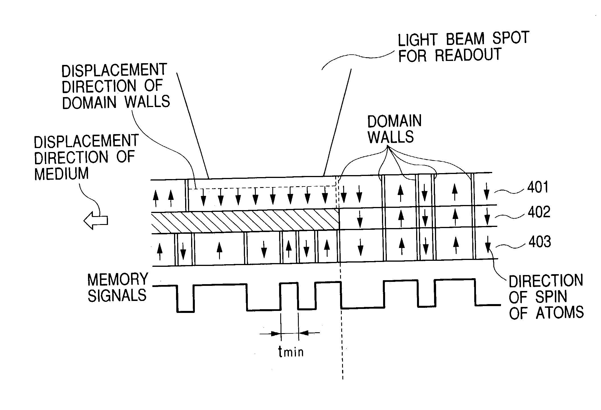
However, at the position where the temperature comes to temperature Ts that is vicinal to the Curie temperature of the switching layer, such exchange coupling force weakens, and hence only domain walls in the displacement layer which have small domain wall coercive force displace alone to the high-temperature side.
However, magnetic films for magneto-optic recording mediums which have been developed so far do not presuppose their use in the DWDD readout method, and hence they have little taken account of recording and readout performance for ultramicromarks.
Especially where the memory mark length is about 0.15 .mu.m or less in the existing TbFeCo magnetic films, lack of memory may occur when recorded or any good jitter value can not be attained, thus there has been a problem that memory marks have insufficient storage stability.

Method used


Image

  • Magneto-optic recording medium recordable at ultrahigh recording density
  • Magneto-optic recording medium recordable at ultrahigh recording density
  • Magneto-optic recording medium recordable at ultrahigh recording density

Examples


Embodiment Construction

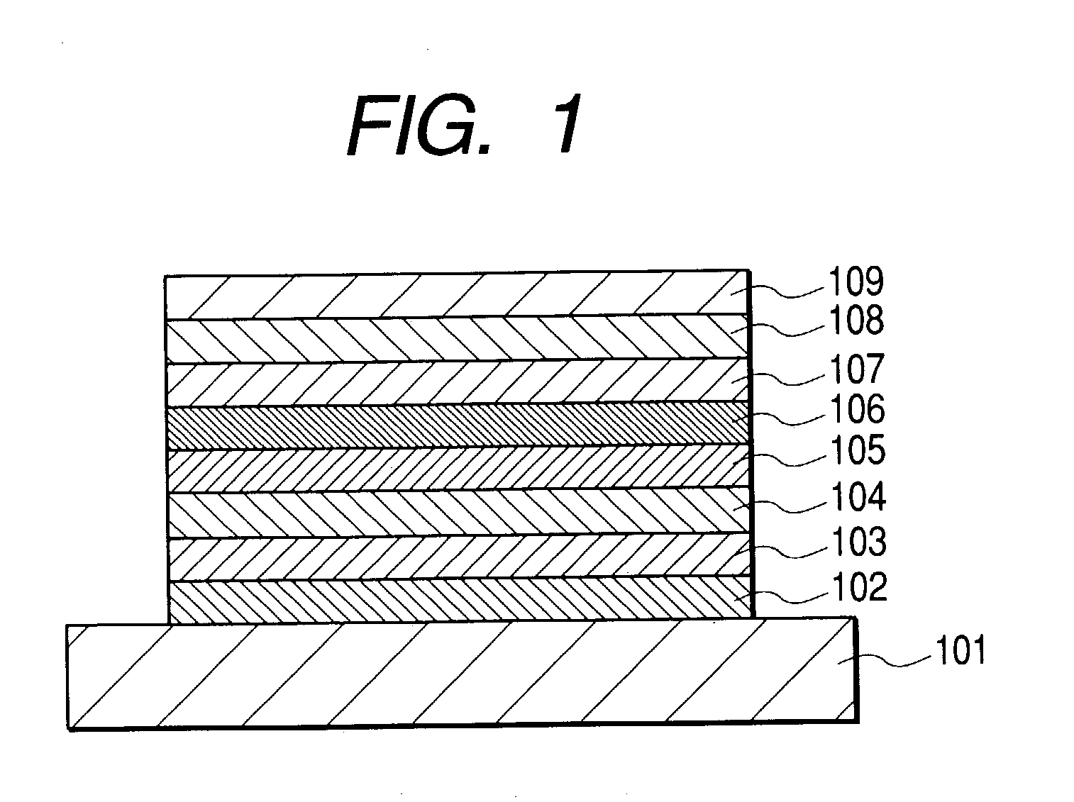
[0033] A direct-current magnetron sputtering system was fitted with targets of B-doped Si and also Gd, Tb, FeCr and CoCr, and a polycarbonate substrate in which guide grooves for tracking were formed was fastened to a substrate holder. Then, the inside of a chamber was evacuated by means of a cryopump until it came to a high vacuum of 2.times.10.sup.-5 Pa or less. Thereafter, Ar gas or Kr gas was fed into the chamber as its inside was kept evacuated, and the targets were sputtered rotating the substrate to form each layer. When a SiN layer is formed, N.sub.2 gas is fed in place of Ar gas to carry out direct-current reactive sputtering to form the film.

[0034] In the first place, Ar gas and N.sub.2 gas were made to flow into the chamber and the pressure was set to the desired value by regulating conductance, where an SiN layer was formed as the first dielectric layer in a thickness of 35 nm.

[0035] Magnetic films are formed in a chamber different from that for the dielectric layer beca...


PUM


Abstract

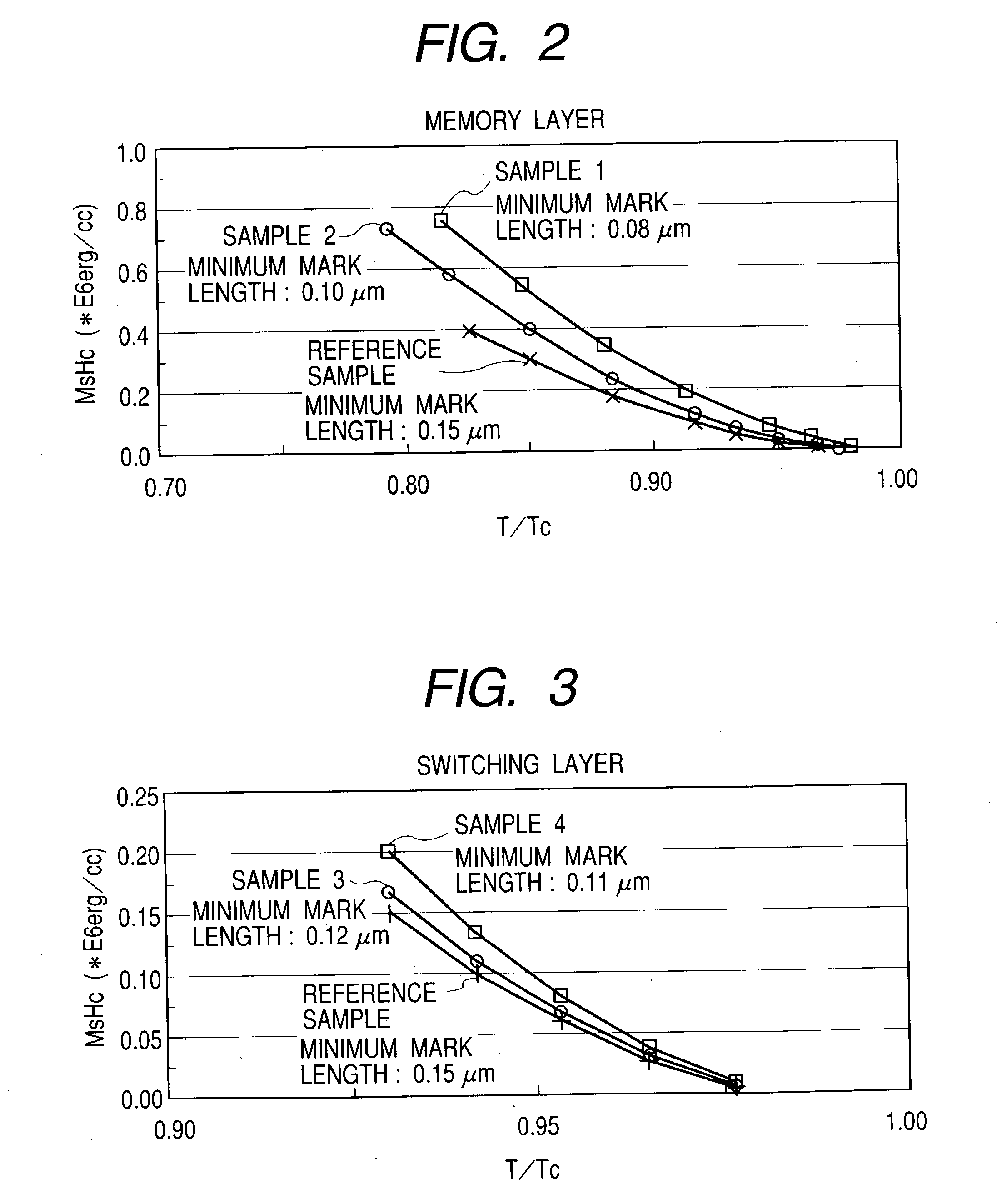
There is provided a magneto-optic recording medium which suits the DWDD readout method and enables stable formation of domains even when ultramicromarks are recorded. The magneto-optic recording medium has a memory layer and a switching layer as magnetic films and, when produced, conditions for forming the magnetic films are so surveyed that the product of saturation magnetization Ms and coercive force Hc, MsHc, is maximized. An MsHc (106 erg / cc) of the memory layer is 15.8 (T / Tc-1) or more where temperature is represented by T (K) and Curie temperature of the memory layer by Tc (K).

Description

[0001] 1. Field of the Invention[0002] This invention relates to a magneto-optic recording medium for ultrahigh-density recording.[0003] 2. Related Background Art[0004] As rewritable recording mediums, various magnetic recording mediums have been put into practical use. In particular, magneto-optic recording mediums in which the heat energy of a semiconductor laser is used to write magnetic domains in a magnetic thin film to record information and the magneto-optic effect is utilized to read this information are expected as large-capacity commutative mediums which can perform high-density recording. In recent years, with the trend of digitization of animated images, there is an increasing demand for the enhancement of recording density of such magnetic recording mediums to provide recording mediums having much larger capacity.[0005] In general, the linear recording density of an optical recording medium depends greatly on the laser wavelength of a readout (or reproduction) optical s...

Claims


Application Information

Patent Timeline
IPC IPC(8): B32B9/00G11B11/105
CPCG11B11/10515G11B11/10591G11B11/10584G11B11/10582
Inventor MIYAKOSHI, TOSHIMORI
Owner CANON KK
Learn More