System for controlling irrigation applications

a technology of irrigation system and irrigation system, applied in process and machine control, process control, process control, etc., can solve the problems of water percolation beyond the root zone and waste, and sandy soils do not retain water well

Inactive Publication Date: 2003-09-25
BARNES ANDREW
View PDF12 Cites 133 Cited by
  • Summary
  • Abstract
  • Description
  • Claims
  • Application Information

AI Technical Summary

Problems solved by technology

Sandy soils do not retain water well, so less water with more frequency is needed, or water will percolate beyond the root zone and be wasted.
If too much water is applied, the water will percolate beyond the root zone and be wasted.
Although prior art systems have used ET computations to determine watering schedules for irrigation systems, one drawback of such system 10s has been that they have relied upon current or historical meteorological data.
These systems are generally not cost-effective for most small landscape sites and can require on-site system operators.
Thus, a drawback of conventional irrigation control system 10s is the lack of capability to account for all the changing weather-related parameters (such as rainfall, temperature, solar radiation, wind speed, humidity, seasonal plant requirements, forecasts, etc.) at a cost-effective price.
Use of conventional irrigation control system 10s results in a deviation from optimum watering schedules and causes either more water to be used or not enough water, which, in turn, stresses the plants.
Additionally, communities throughout the United States and the world share an uneasy reliance on both surface and sub-surface water supplies.
Thus, farmers' worry there won't be enough water to feed their crops.
And environmentalists worry that too little water is allowed for natural purposes.
Additionally, businesses worry that a lack of water will dampen the availability of jobs.
This results in an enormous waste of fresh potable water needed for internal uses.
Unfortunately the major cause for over watering is the lack of irrigation information, and technology to control waste.
Consequently, there are so few types of landscape irrigation controllers, other than timers.
These timers do not know when it is raining, nor do they know over watering must stop.
The complexity of a multi-station timer switches opening the sprinkler valves for a specific amount of time daily, are confusing and very labor consuming.
The inefficiency is in the fact they deliver water based upon the time of day, regardless of the moisture levels in the soil.
Moreover, it is not convenient for most ratepayers to check the moisture levels in their lawns, and strictly have relied upon timers to do so.
Since moisture probes are extremely sensitive to placement and orientation within the soil itself.
The performance is normally at a lesser level, resulting in either over or under watering.
1. Relatively inexpensive controllers that are capable of executing an irrigation program. These controllers are not capable of changing the set irrigation program in any way to take account of differing water needs of plants occasioned by variations in meteorological conditions. Such controllers will, if the irrigation program is not regularly modified inevitably waste considerable quantities of water, since it will be programmed to supply sufficient water to serve the needs of the plant being irrigated during periods when plant demand for water is low.
Additionally, such controllers are incapable of responding to occurrence of rain periods unless coupled to some specialist sensor designed for the purpose.
Whilst such sensors are known they tend to be either expensive (and consequently little used) or unreliable (and again little used).
The potential to save water by in effect harvesting rainfall by discontinuing irrigations until that rainfall finds its way into the root-zone and is transpired by the plants, is lost unless the controller can be manually de-activated.
When managing large numbers of such controllers, particularly over a wide area, it is generally not possible to manually de-activate them and re-activate them when irrigation should commence.
2. More expensive controllers that can alter the frequency and amount of irrigation, either up or down, as time passes in an effort to match applications to plant requirements.
This type of controller is an improvement upon the first described type of controller, but is still arbitrary and inflexible as it relies on averages that must inevitably waste water when the predicted conditions do not occur.
However, such controllers do not utilize localized rainfall measurement and consequently irrigation management depends upon rainfall information indicative of a wider area than the irrigation area.
Water wastage can result.
Further, these controllers must be part of a very wide network that means that over a wide area very considerable telephony or radio costs are necessarily involved.
As stated above, the systems currently available are very expensive and are targeted towards the golf and high profile large-scale markets.
Additionally, the systems do not overcome all of the problems disclosed above.
Communication is another costly component.
This is a labor-intensive installation and usually involves special machinery.
The cable is most often buried below grade and requires site restoration at the completion of the project especially if the installation is for an existing site.
It is possible to have a phone line at each controller for communication or use cellular technology but cost is very high for thiss type of connection.
However, most irrigation manufacturers still use expensive frequencies and equipment.
By restricting the amount of water applied to the turf grass, the rate of growth may be limited to reduce the frequency of mowing.

Method used


Image

  • System for controlling irrigation applications
  • System for controlling irrigation applications
  • System for controlling irrigation applications

Examples


examples 1

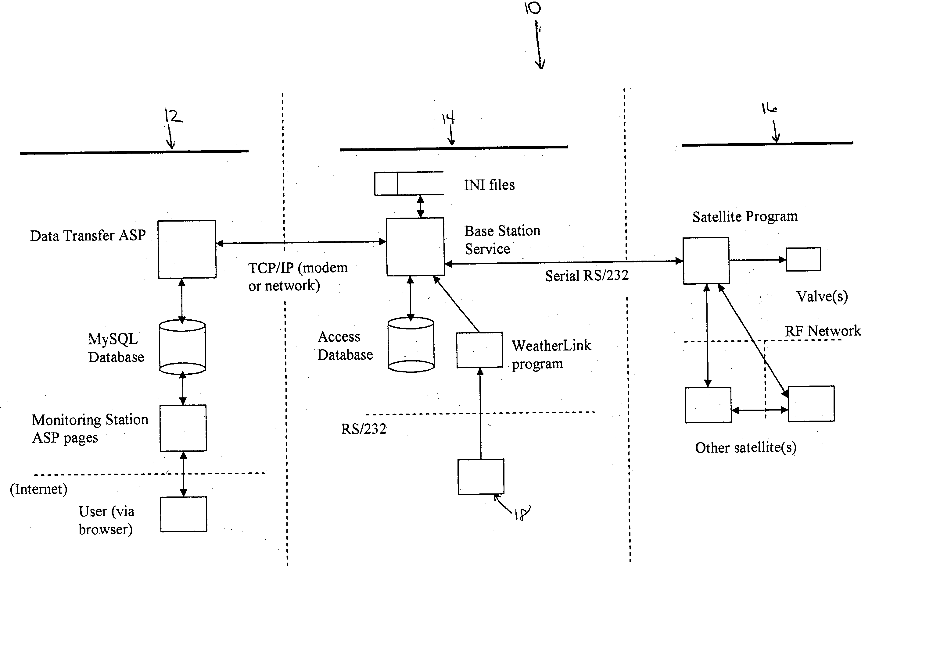
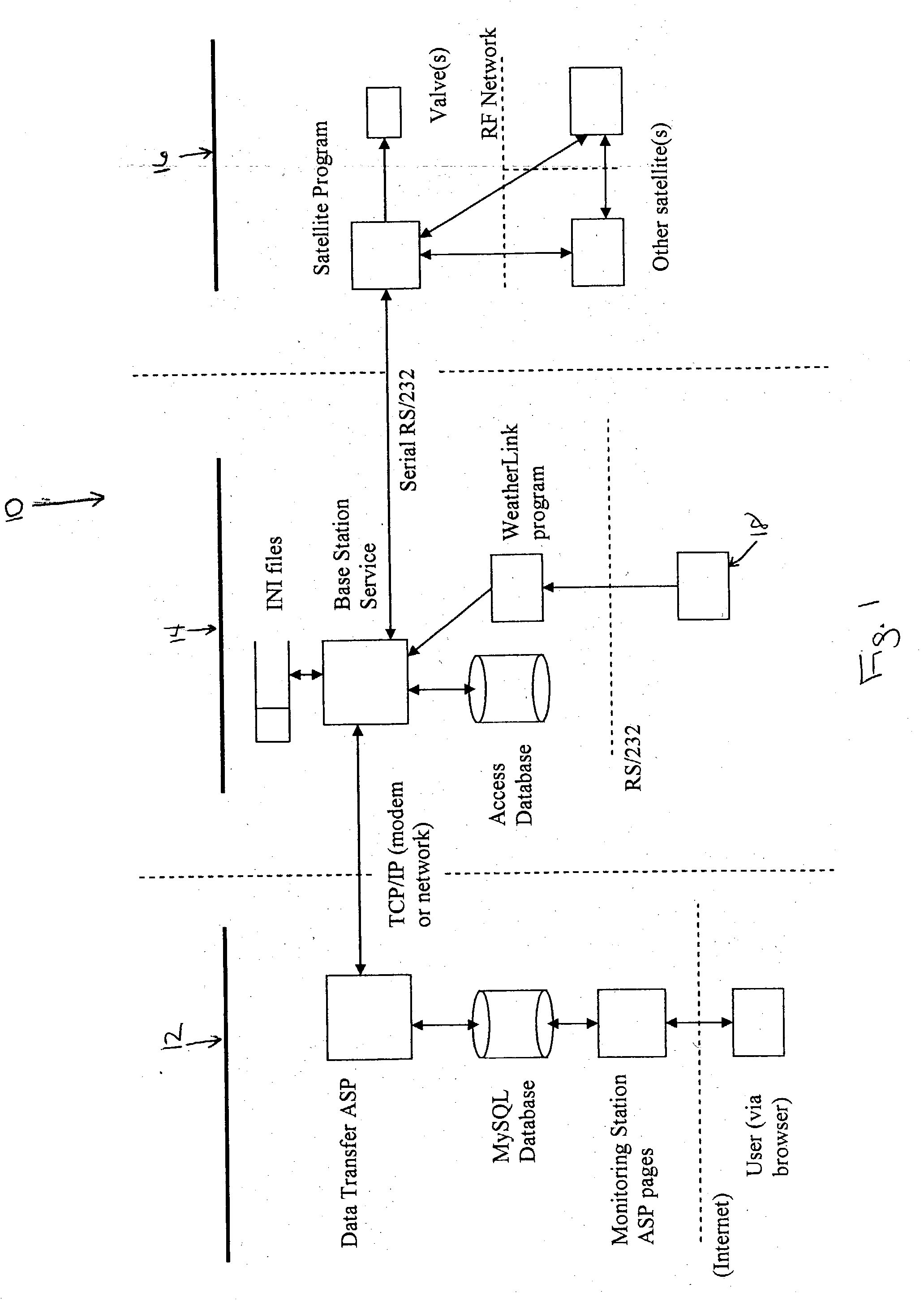
[0065] The monitoring station is installed on a single host server with an "always-on" connection to the Internet. The software runs as a standard web site, under a single base URL and IP address as shown in FIG. 3. It has two primary interfaces (i.e., top-level pages),one for automatic communications (used by the Base Stations) and one for manual use (accessed as a standard web page via a browser).

[0066] Data Transfer Asp

[0067] This set of ASP pages handles communication between the Monitoring Station and the Base Station(s). When a Base Station initiates contact with the Monitoring Station, it requests the appropriate ASP page, which handles the conversation on the Monitoring Station's side. These pages collect the information reported by the Base Station and send down instructions generated by the user (if any exist).

[0068] MySQL Database

[0069] This is the central data repository for the system 10. It includes information about all Base Stations in its network, including informat...

example 2

[0102] Installation Process

[0103] Install the Monitoring Station. The Monitoring Station should be running and connected to the Internet before proceeding to the following steps. Install a proper version of Crystal Reports. Version 8.5 Professional was used in the testing and development of the site.

[0104] Run the MySQL.sql script to setup the MySQL database.

[0105] Create an ODBC DSN to the database.

[0106] Create a virtual directory or web site for the web site files. The files in the "Virtual Directory" folder of the Liquid Assets source code should be put at the root of the web site or virtual directory. Be sure to allow parent paths since the pages use server side includes to the files in the "Include" and "CustomInclude" source code folders as well.

[0107] Modify the "DatabaseConstants.asp" file in the "Custominclude" folder. Specifically, change the "database_connection_string" constant to use the right DSN, MySQL user name, and MySQL password.

[0108] Modify the "Security.asp" fi...

example 3

[0229]

4 INSTALLATIONMODE.C(ABRIDGED) . . . . . void PollForInstallationMode( ) { int1 in_installation_mode; in_installation_mode = PollForInstallationButtonPush( ); if(!in_installation_mode) { return; } TurnOffDebugLED( ); ResetSchedule( ); . . . . . while (in_installation_mode) { / / Send a ping SendSmallMessage(SMALL_MESSAGE_TYPE_PING, MESSAGE_DIRECTION_TOWARDS_CHILD_SATELLITES); ResetSerialReceiver( ); / / Wait for a response. while (in_installation_mode) { if(PollForRFPingReply( )) { / / Got Reply. FlipDebugLED( ); . . . . . break; } in_installation_mode = in_installation_mode && !PollForInstallationButtonPush( ); } in_installation_mode = in_installation_mode && !PollForInstallationButtonPush( ); } ResetSchedule( ); . . . . . }

[0230]

5 SCHEDULEBUILDER.CPP(ABRIDGED) . . . . . void ScheduleBuilder::PollForNewSchedule( ) { . . . . . if(!IsReadyForNewSchedule( )) { return; } . . . . . / / - Build the schedule data. ScheduleData schedule_data; BuildCurrentSchedule(schedule_data); / / -Crea...


PUM


Abstract

A system for controlling an irrigation system having a monitor for remotely monitoring and communicating irrigation related information in the system, a controller in communication with the monitoring means for receiving the information, processing the information to coding functional commands, and sending the information to the irrigation system, and a decoder in communication with the controller for decoding the coded signal at specific sites in the irrigation system and performing a function based upon the signal. A method for remotely controlling an irrigation system by providing the system with irrigation related information and remotely modulating the system based upon the irrigation related information. A software program for controlling an irrigation system, the program having a CPU for running the program and an algorithm for controlling the irrigation system.

Description

[0001] This patent application claims the benefit of priority under 35 U.S.C. Section 119(e) of U.S. Provisional Application No. 60 / 344,656, filed Dec. 26, 2001, which is incorporated herein by reference.[0002] 1. FIELD OF THE INVENTION[0003] The present invention relates to a system for controlling irrigation systems. More specifically, the present invention relates to a remote system for automatically controlling irrigation systems.[0004] 2. DESCRIPTION OF RELATED ART[0005] The term evapotranspiration (ET) is used in the irrigation field to quantify how much water has been lost from soil through transpiration by plants. An ET value is calculated using actual meteorological data obtained from meteorology stations. The factors typically used to calculate an ET value are temperature, solar radiation, wind speed, vapor pressure or humidity, and barometric pressure. A change in one or more of these parameters can have a direct effect on the ET value used to determine when and how much ...

Claims


Application Information

Patent Timeline
Patent Type & Authority Applications(United States)
IPC IPC(8): A01G25/16G05B23/02
CPCA01G25/167G05B2219/2625G05B19/042
Inventor BARNES, ANDREW
Owner BARNES ANDREW
Why Eureka
Try Eureka