Method of measuring copper ion concentration in industrial electrolytes

a technology of industrial electrolytes and ion concentrations, which is applied in the direction of liquid/fluent solid measurement, instruments, material analysis, etc., can solve the problem of inability to control processes in real time, and achieve high reproducibility and reliability, easy programming, and high selectivity of electrochemical measurements.

Inactive Publication Date: 2003-10-02
K G H M POLSKA MIEDZ SPOKA AKCYJNA
View PDF2 Cites 10 Cited by
  • Summary
  • Abstract
  • Description
  • Claims
  • Application Information

AI Technical Summary

Benefits of technology

0023] The carried out studies proved that voltamperometry (CV) and chronoamperometry (CQA) used alternatively according to concentration range are the most suitable methods to measure copper ion concentration in industrial electrolytes because both methods show high selectivity of electrochemical measurements. Using an ultramicroelectrode as a working gold or platinum microprobe of a diameter from 1 to 50 .mu.m ensures the possibility of achieving measurement accuracy of 1% even at the highest concentration up to 60 g/l.
0024] The method presented in the invention is also advantageous because it does not require any initial treatment/processing of the industria

Problems solved by technology

It is also impossible to control the processes in real time because t

Method used


Image

  • Method of measuring copper ion concentration in industrial electrolytes
  • Method of measuring copper ion concentration in industrial electrolytes
  • Method of measuring copper ion concentration in industrial electrolytes

Examples


example i

The Procedures Carried Out in Voltammetric Method (CV) are Described

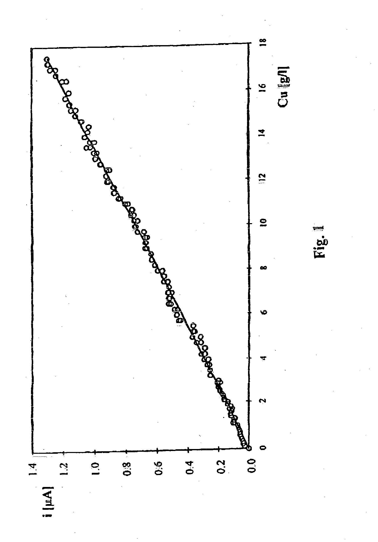
[0033] Stage 1. Voltammetric method is used for obtaining a calibration curve for current density value in relation to copper ion concentration in 9 industrial solutions of the laboratory determined ion concentration in the range from 0.1 to 25 g / l. The measurements are carried out at a gold microprobe of a diameter 25 .mu.m at applied initial potential of -900 mV changing in time at the velocity of 200 mV / s, at an electrolyte temperature of about 20.degree. C. using a platinum reference electrode in the form of a plate the surface of which is 0.3 cm.sup.2.

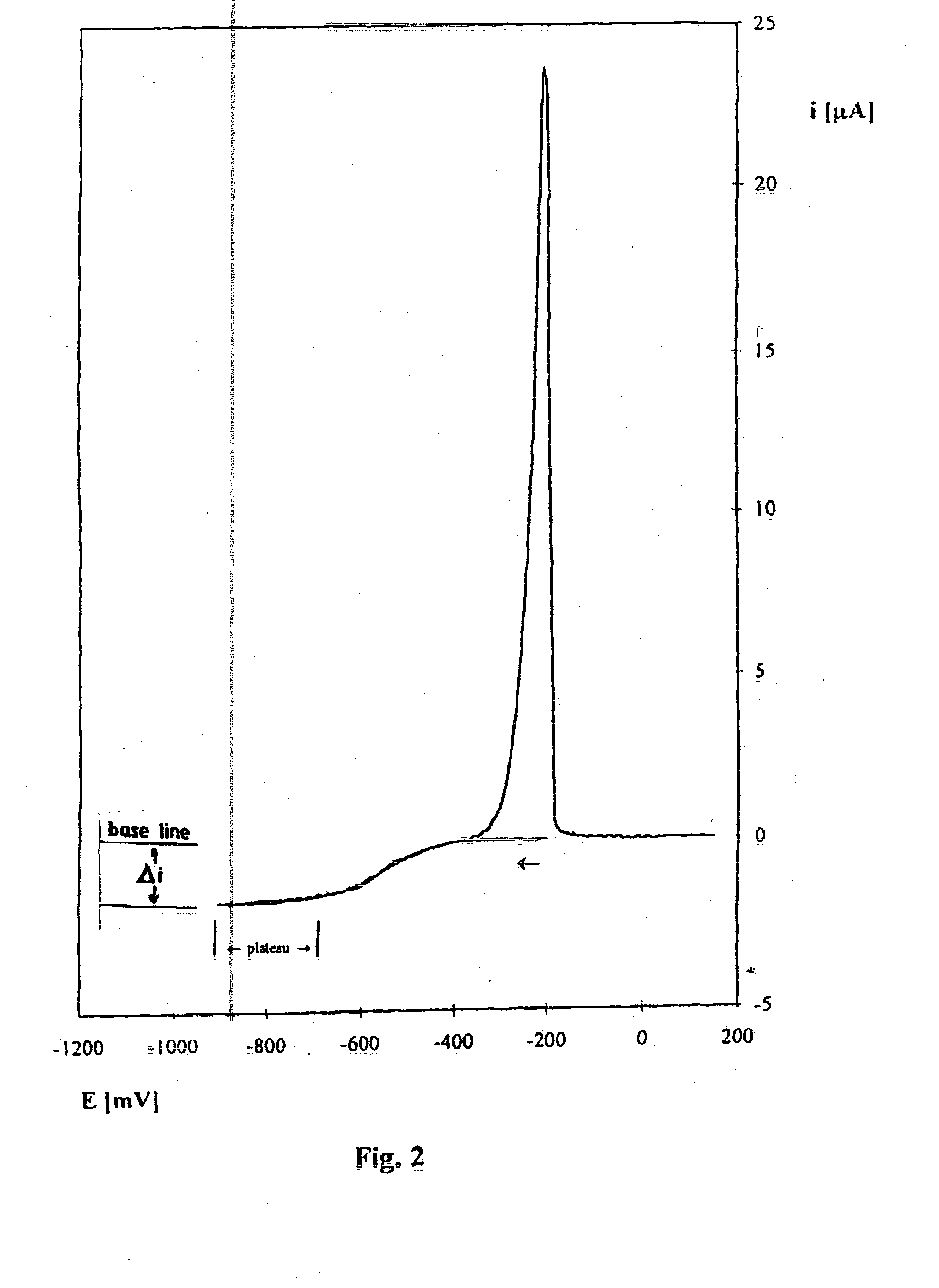
[0034] In order to determine copper ion concentration in the studied industrial solution, voltammetric current potential curve is registered and concentration is found from the calibration curve of current density value in relation to copper Cu(II) ion concentration in g / l.

[0035] Stage 2. Voltammetric method is used for obtaining a calibration curve after having i...

example ii

The Procedures Carried Out in Chronoamperometric (CA) Method are Described

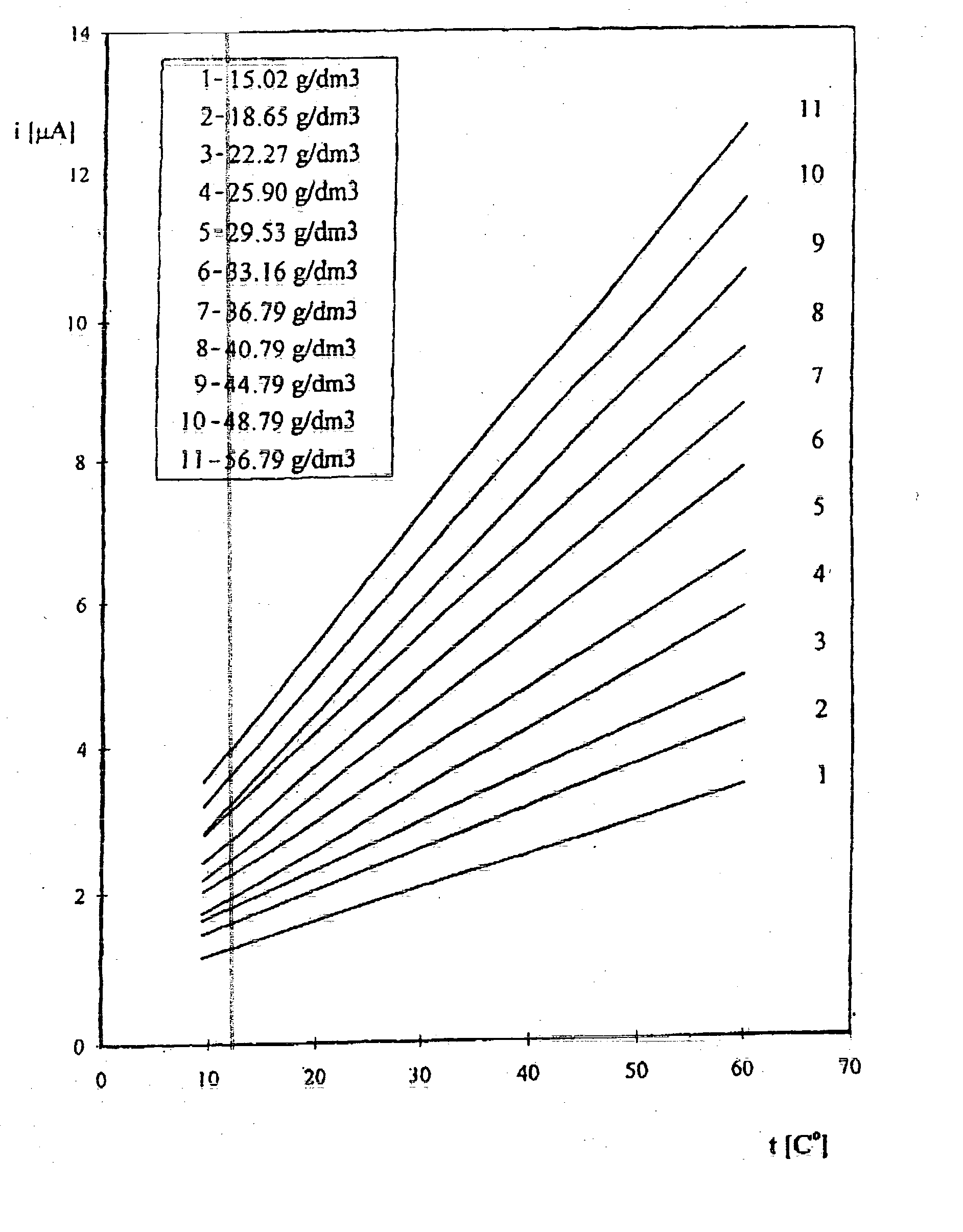
[0039] Stage 1. Using chronoamperometric method a family of calibration curves / relationships of current density value in relation to electrolyte temperature for sufficiently high number (dozen or so) of ion concentrations in the industrial electrolyte is obtained by adding in succession sulphate copper portions, resulting concentrations being determined in laboratory by another analytical method. The measurement of a curve is carried out at a gold microprobe of a diameter 25 .mu.m, at an applied potential of -400 mV duration of which is 84 ms using a reference electrode in the form of a copper plate, the surface of which is about 0.3 cm.sup.2.

[0040] Calibration curves / relationships for selected in the studied range temperatures in current density vs. copper ion concentration co-ordinates are calculated from the following relation:

y=a(t).times.Cu+b(t)

[0041] where

[0042] a--sensitivity coefficient,

[0043] t--tempe...


PUM


Abstract

The method consists in registering curves by cyclic voltammetry method in the range of copper ion concentration up to 20 g/l or alternately by chronoamperometric method in the range of concentration from 20 to 60 g/l. A platinum or gold microprobe of a diameter in the range from 1 to 50 um and a copper plate reference electrode are used. The value of current density read off from said curves is compared to the calibration curves previously determined by standard additions method. For high concentration in the range from 20 to 60 g/l the calibration curves obtained in the range of temperatures from 15 to 60° C. are registered.

Description

FIELD OH THE INVENTION[0001] This invention relates to a method of measuring copper ion concentrations in industrial electrolytes in order to maintain optimum electrolyte composition which enables to obtain the highest quality copper at high current density efficiency of copper electrorefining process.[0002] In order to obtain the highest quality copper the following chemical conditions must be fulfilled:[0003] high concentration of Cu.sup.++ at cathode surface,[0004] steady level of surface-active additions concentration,[0005] absence of slime particles at cathode surface,[0006] low concentration of impurities in an electrolyte,[0007] minimising temperature gradient in electrolyte tank.[0008] Besides it is particularly important to measure continuously copper ions concentration in an electrolyte. The continuous measurement of said concentration guarantees maintaining a proper concentration level of copper and sulphuric acid in circulating electrolyte. In this way, optimum usage of...

Claims


Application Information

Patent Timeline
IPC IPC(8): G01N27/48G01N27/49
CPCG01N27/49G01N27/48
Inventor LOS, PRZEMYSLAWFUGLEWICZ, BOGUSLAWMALACHOWICZ, GRZEGORZGLADYSZ, OLYMPIAPLINSKA, STANISLAWAKOZAKIEWICZ, ANDRZEJBAS, BOGUSLAWNOWAK, JACEKURBANOWICZ, KRZYSZTOFSLOMKA, MAREKRAPACZ, ANDRZEJ
Owner K G H M POLSKA MIEDZ SPOKA AKCYJNA
Why Eureka
Try Eureka