Polarized wave scrambler and optical signal transmission apparatus

a polarized wave and optical signal technology, applied in the direction of instruments, optical fibres with polarisation, polarising elements, etc., can solve the problems of high cost, low reliability, and difficult to reduce cost, and achieve low cost, stable and easy-to-manufacture effects

Inactive Publication Date: 2003-10-02
FUJITSU LTD
View PDF18 Cites 12 Cited by
  • Summary
  • Abstract
  • Description
  • Claims
  • Application Information

AI Technical Summary

Benefits of technology

0041] It is a general object of the present invention to provide a polarized wave scrambler and an optical signal transmission apparatus in which the above disadvantages are eliminated. A more specific object of the present invention is to pr...

Problems solved by technology

The polarized wave scrambler (1) has a complex structure and therefore it is hard to reduce cost.
Further, mechanically moving parts may cause a problem of durability for the polarized wave scrambler and therefore, the reliability is low.
For the polarized wave scrambler (3) using the Lithium Niobate (LiNbO.sub.3) modulator, the cost of the Lithium Niobate (LiNbO.sub.3) modulator is high.
Therefore, the polarized wave scramblers (1)...

Method used


Image

  • Polarized wave scrambler and optical signal transmission apparatus
  • Polarized wave scrambler and optical signal transmission apparatus
  • Polarized wave scrambler and optical signal transmission apparatus

Examples


first embodiment

[0066] A first embodiment according to the present invention will be explained.

[0067] Fig.6 shows a block diagram of an optical signal transmission apparatus using a polarized wave scrambler according to the first embodiment of the present invention.

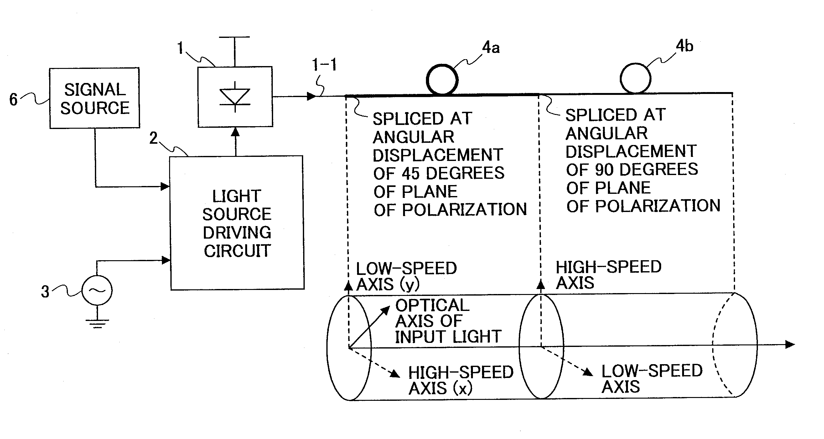
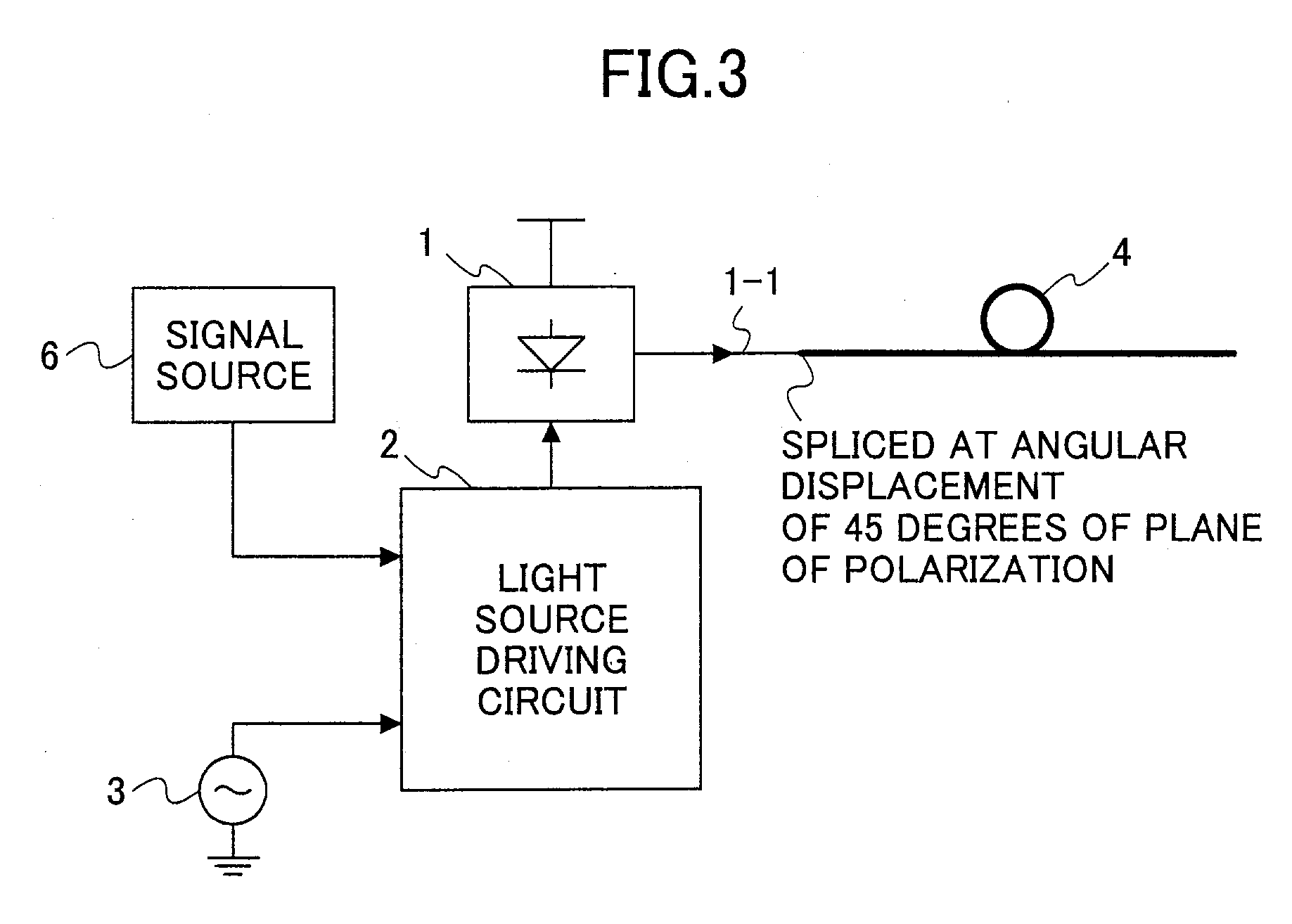
[0068] In Fig.6, reference numeral 1 shows the light source that supplies the linearly polarized optical signal, for example a laser diode. It is well known that the laser diode supplies the linearly polarized light. Reference numeral 1-1 shows a pig-tail fiber that guides the light supplied from the light source 1 outside the light source 1.

[0069] Reference numeral 2 shows a light source driving circuit that supplies a driving current to the light source 1 and the light source driving circuit 2 is usually composed of a circuit of a current-switch-type.

[0070] Reference numeral 3 shows an oscillator that supplies a signal having a lower frequency than a frequency of light, which signal modulates the driving current supplied from the light...


PUM


Abstract

Abstract of Disclosure The present invention provides a polarized wave scrambler and an optical signal transmission apparatus in which polarization mode dispersion, which causes degradation of a transmitted waveform, is suppressed, and which can be easily manufactured and are low-cost and stable. A polarized wave scrambler has a first polarization maintaining optical fiber and a second polarization maintaining optical fiber, wherein a constant component of a phase difference characteristic for optical frequency between a high-speed axis and a low-speed axis of the first polarization maintaining optical fiber is equal to that of the second polarization maintaining optical fiber, and a slope for optical frequency of the phase difference characteristic of the first polarization maintaining optical fiber is different from that of the second polarization maintaining optical fiber, wherein a plane of polarization of the linearly polarized optical signal is set to an angle between the high-speed axis and the low-speed axis of the first polarization maintaining optical fiber and the linearly polarized optical signal is supplied to the first polarization maintaining optical fiber, and wherein the first polarization maintaining optical fiber and the second polarization maintaining optical fiber are spliced such that the high-speed axis of the first polarization maintaining optical fiber corresponds to the low-speed axis of the second polarization maintaining optical fiber, and the low-speed axis of the first polarization maintaining optical fiber corresponds to the high-speed axis of the second polarization maintaining optical fiber.

Description

Background of Invention[0001] 1. Field of the Invention[0002] The present invention generally relates to a polarized wave scrambler and an optical signal transmission apparatus in which a wave transmission of an optical communication system does not have polarization dependant characteristics, and more particularly to a polarized wave scrambler and an optical signal transmission apparatus in which polarization mode dispersion that degrades a transmitted waveform is suppressed, and which can be easily manufactured and are low-cost and stable.[0003] In optical communication systems, first put to practical use around 1950 in long distance optical communication systems, a regenerative repeater that has so called 3R functions, namely reshaping, retiming and regenerating, is used to relay a transmission signal.[0004] In this system, the structure of the regenerative repeater is complex and therefore, the regenerative repeater has many adjustment points to implement the 3R functions in the...

Claims


Application Information

Patent Timeline
IPC IPC(8): G02B6/024G02B6/10G02B6/14G02B6/34G02B27/28H04B10/25
CPCG02B6/105G02B6/2786G02B6/274G02B6/14
Inventor NAKAJIMA , ISAO
Owner FUJITSU LTD
Why Eureka
Try Eureka