Inkjet printer and printer head

a printer head and inkjet technology, applied in printing and other directions, can solve the problem of easy blockage of the ink flow path

Inactive Publication Date: 2003-10-23
RICOH KK +2
View PDF0 Cites 27 Cited by
  • Summary
  • Abstract
  • Description
  • Claims
  • Application Information

AI Technical Summary

Problems solved by technology

Since an ink flow path or conduit of the inkjet head is very narrow, the ink flow path may be easily clogged if the ink flow path surface is not treated properly.

Method used


Image

  • Inkjet printer and printer head
  • Inkjet printer and printer head
  • Inkjet printer and printer head

Examples


example 1

[0134] A method of forming an ink repellent layer on the orifice plate is described in the following. An outline of this process is shown in FIG. 5. In the following, the face that has a jetting nozzle is called a main face, and the opposite face is called a rear face.

[0135] An orifice plate made of SUS 304 having a nozzle outlet of 40 m and a thickness of 80 m was prepared. The structure is shown in step (a) of FIG. 5. Tape No. 966 manufactured by 3M Co. as masking tape 22 was stuck on the main face, and then a pressure of 1.0.times.10.sup.5 kg / m.sup.2 was applied thereto for 30 seconds as shown in step (b) of FIG. 5.

[0136] Thereafter, a 15 wt % aqueous solution of poly(vinyl alcohol) (the number of repeating units is 1500) was coated on the rear face. The coating was dried at room temperature to vaporize water solvent, resulting in a mask layer 23 as shown in step (c) of FIG. 5.

[0137] The depth of forming the ink repellent layer in the inkjet nozzle is adjusted by controlling a th...

example 2

[0150] Example 1 was carried out, except that in preparing an ink-philic composition, Snow Tex IPA-ST as colloidal silica was changed to MT-ST. IPA-ST contains isopropanol as a solvent, but MT-ST contains methanol as a solvent.

[0151] The ink-philic materials in this example is repelled by the ink repellent layer and is not coated with the ink repellent material. The ink-philic material can be coated on the adhesive, and can form an ink-philic layer having a contact angle with water of about 200.

[0152] After the forming of the ink-philic layer, ink was filled in the ink chamber, and printing of images was carried out. Ink was jetted out from all of the nozzles to form desired images.

[0153] Accordingly, the ink-philic material for making the ink-philic layer was able to jet out desired amounts of ink even when a dispersant for colloidal silica changes from isopropanol to methanol.

example 3

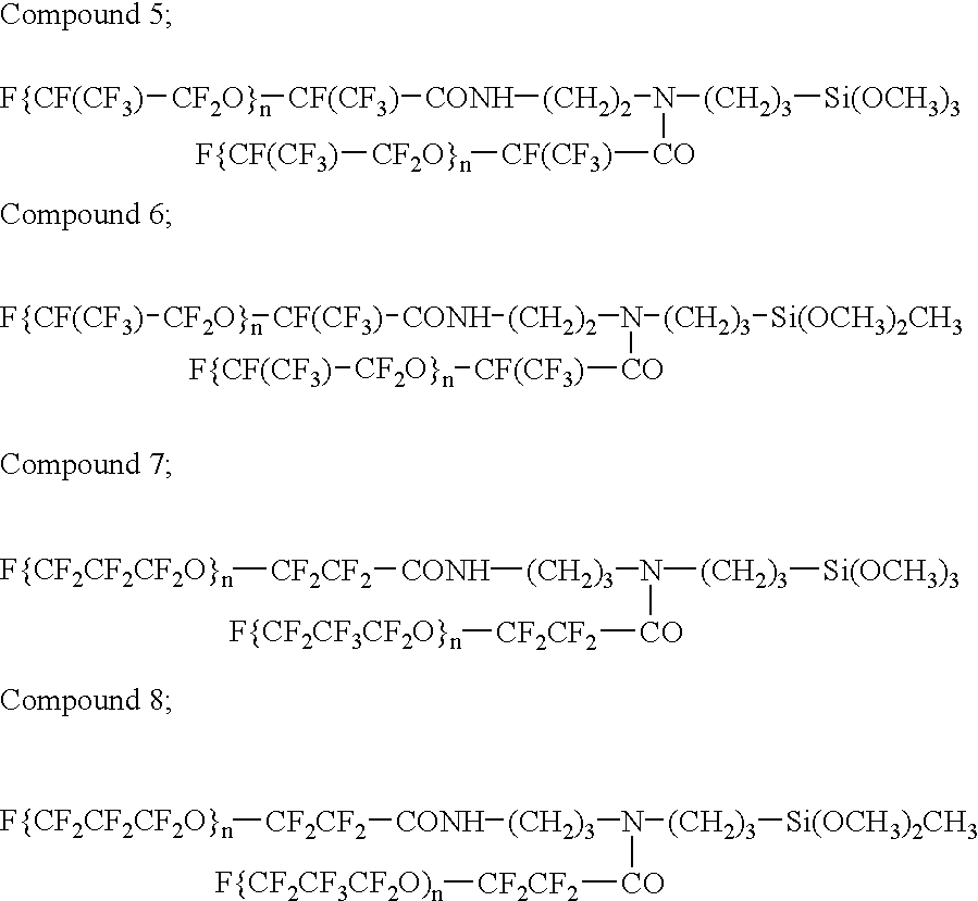
[0154] Example 1 was carried out, except that compound 2 was used for compound 1. As a result, it was confirmed that the ink repellent material repels the ink-philic material and does not form a membrane on the ink-repellent layer. After the forming of the ink-philic layer, ink was filled in the ink chamber and printing of images was conducted. Ink was jetted out from all of the nozzles to form desired images.

[0155] From the test result, it was revealed that even when the ink repellent material is changed from compound 1 to compound 2, the inkjet head was able to jet out desired amounts of ink and that the inkjet printer according to this example was able to make images stably.


PUM


Abstract

An inkjet head having an ink flow path communicated with an ink chamber to an inkjet nozzle and having an orifice plate to which the nozzle is formed. An ink-philic layer is formed on the surface of the ink flow path, and an ink repellent layer is formed on the surface of the orifice plate where the nozzle is formed. The ink-philic layer is made of amorphous silica or inorganic polymer of colloidal silica bonded with a polymer of (SiOR), and the ink repellent layer contains a compound having perfluoropolyether chain and alkoxysilane residue as a terminal.

Description

[0001] The present invention relates to an inkjet printer, an ink head for the printer and a method for making the same.PRIOR ART[0002] Inkjet printers have become very much popular not only in offices, but also at homes, because they are small-sized, compared to electrophotographic printers. Image formation by inkjet printers is performed by jetting ink drops on recording medium such as paper from a nozzle or nozzles to fix the ink on the recording medium.[0003] If ink sticks to positions near the nozzle and it is dried, new jetted ink makes contact with the dried ink to change its jetting direction. Therefore, in the conventional inkjet printers, the surface of the nozzle of the inkjet head is treated with an agent that repels ink, i.e. ink-repellent treatment. Further, there is also provided a wipe mechanism for wiping the side surface of the nozzle.[0004] Since an ink flow path or conduit of the inkjet head is very narrow, the ink flow path may be easily clogged if the ink flow ...

Claims


Application Information

Patent Timeline
Patent Type & Authority Applications(United States)
IPC IPC(8): B41J2/16
CPCB41J2/1606B41J2/1645B41J2/1623B41J2/1612
Inventor SASAKI, HIROSHIKUROSAWA, MAKOTOSUZUKI, YOSHINARI
Owner RICOH KK
Why Eureka
Try Eureka