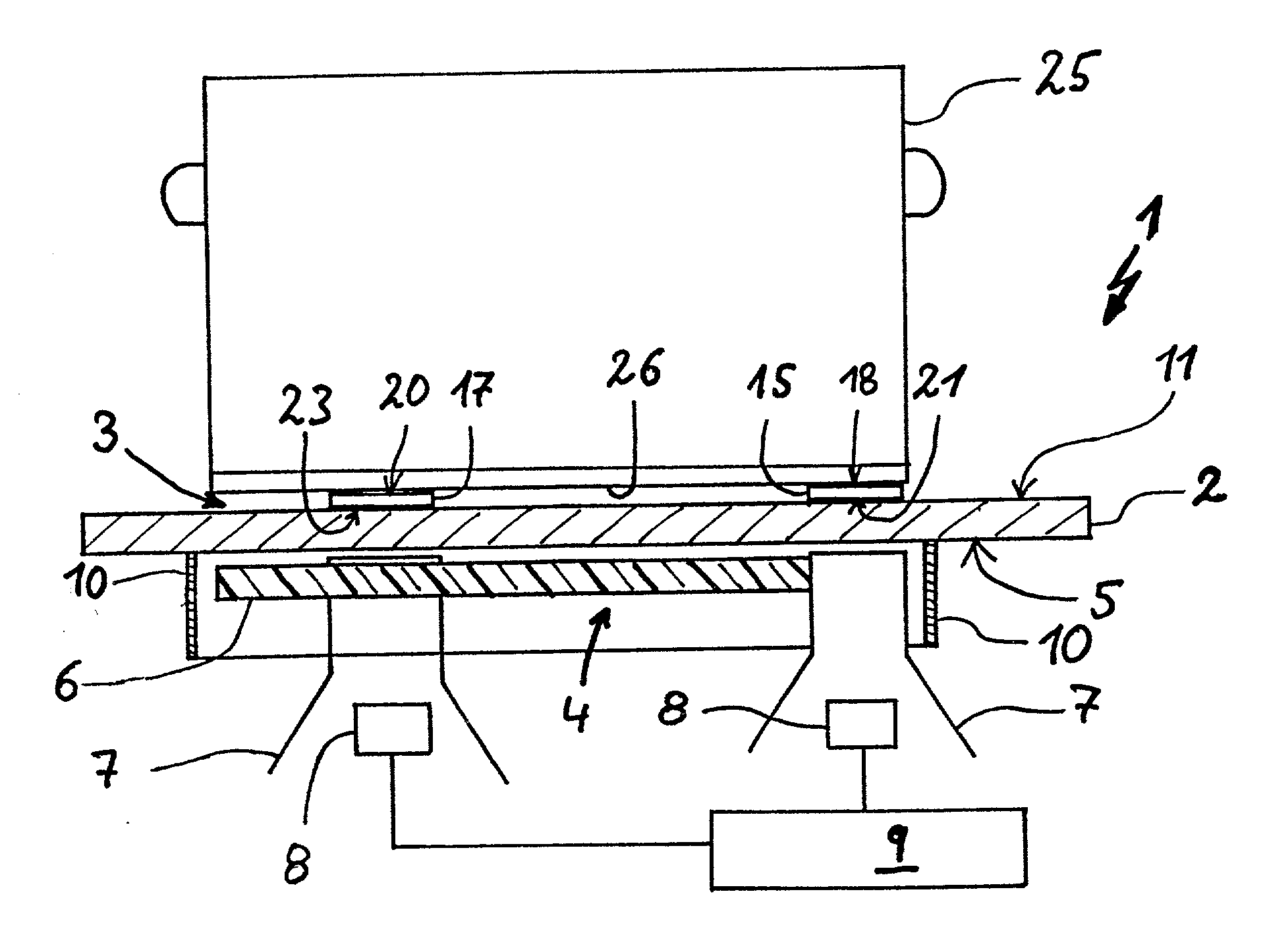
[0008] Particular preference is given to further developments in which the determination of the measuring element temperature takes place from below through the hotplate. This makes it possible to house temperature determination devices of the externally positioned measuring elements, e.g. in a substantially hermetically sealed area below the glass
ceramic plate of a hob in a protected manner. There is no need for lines, cables or the like, which on the plate top lead to the measuring element. For example, directly below a measuring element, a measuring
resistor element can be applied, e.g. by printing, to the inside of the hotplate enabling the measuring element temperature to be determined, whilst utilizing the heat conduction through the hotplate. However, in particular below the hotplate and optionally spaced therefrom, can be positioned at least one
infrared sensor with the aid of which the temperature of the hotplate-facing underside of the measuring element can be determined. The hotplate material should in this case have an adequate transmission for the heat
radiation used for the measurement. As the underside of the measuring element, independently of the cooking vessel characteristics, has a defined emission capacity for heat
radiation determined by the nature of the measuring element and optionally the hotplate surface, such a
system can operate precisely with any cooking
vessel type, without special precautions being necessary on the cooking vessel to ensure a specific radiation capacity. Thus, users of such systems can utilize the advantages of a
temperature measurement by using
infrared sensors, without being involved in capital expenditure in obtaining cooking vessels.
[0009] A measuring element can e.g. be formed by a material
coating applied in self-
adhesive manner to the top of the hotplate, e.g. by a material
coating, particularly a
heat resistant dye or ink or colour coating applied by a thin or thick film process. This brings about a particularly good adhesion of the measuring element to the top of the hotplate and in addition the shape and / or thickness of the measuring element can easily be adapted to the desired measuring element design by controlling the process during coating. For example, suitable colour coatings can be used, such as are employed in the conventional decoration of glass
ceramic surfaces. Application can take place in the same process step. If necessary,
metal particles can be admixed.
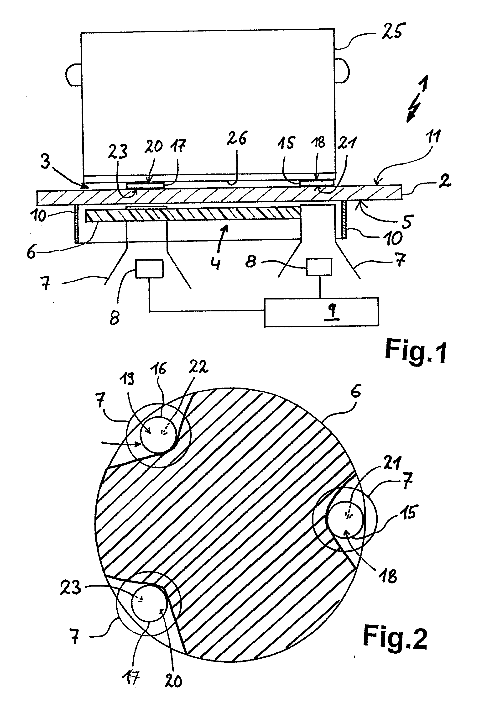
[0012] It can also be appropriate to provide in the vicinity of the cooking zone several mutually laterally spaced measuring elements, which ensures that also in the case of cooking vessel sizes not ideally suited to the cooking
zone size, in each case at least one measuring element provides precise temperature measurement values. It is preferable to have a triangular arrangement of three normally identical measuring elements ensuring that a cooking vessel is supported in stable manner with an adequate base surface on three points and cannot wobble. In order to avoid that a set down pot, saucepan, etc., during stirring does not turn around a
support surface formed by a measuring element, it is advantageous if there is no measuring element in the central area of the heating zone. Generally an arrangement of several measuring elements over a circle is advantageous and the
diameter thereof is slightly smaller or roughly the same as the
diameter of typical cooking vessels to be placed on the corresponding heating zone, so that a support is ensured in the outer marginal area of a cooking vessel bottom.
[0013] The invention, which in the case of preferred embodiments proposes one or more reference measuring surfaces for
infrared temperature measurement from the inside of a glass
ceramic hob, also relates to heating appliances, which are equipped with a temperature determination device according to the invention and in particular
electric heating appliances. It is particularly advantageous for use with
induction cooking units, where the heat for heating set down cooking vessels is provided in the
wall material of the actual cooking vessel, particularly in the cooking vessel bottom, by inductively generated eddy currents. Particularly in the case of such
electric heating appliances the precise determination of the cooking vessel temperature is useful, because an indirect
temperature monitoring, e.g. by monitoring the hotplate temperature, can be imprecise, because there may be large temperature differences between the hotplate and the cooking vessel. Inductive cooking systems are particularly suitable compared with also possible
radiant heating systems, because with the latter normally the at least one measuring element is directly heated from below by heat radiation, so that possibly there can be differences compared with the cooking vessel temperature. With inductive cooking systems it is generally easier to install below the hotplate, e.g. in the vicinity of an
induction coil, one or more heat-sensitive infrared sensors in a protected manner, because in this area, compared with
radiant heating systems, normally much lower temperatures prevail, which can improve the operation and life of the infrared sensors.
