Concentrating photovoltaic cavity converters for extreme solar-to-electric conversion efficiencies

a photovoltaic cavity and conversion efficiency technology, applied in thermal-pv hybrid energy generation, machines/engines, control devices, etc., can solve the problems of wasting the remainder of available energy outside of their limited spectral response, and wasting the excess energy of photons

Inactive Publication Date: 2003-11-20
UNITED INNOVATIONS
View PDF0 Cites 146 Cited by
  • Summary
  • Abstract
  • Description
  • Claims
  • Application Information

AI Technical Summary

Benefits of technology

0010] In accordance with the present invention, a photovoltaic cavity converter (PVCC) module is provided which can operate at a concentration range of about 500 to 1,000 suns and a power output range of a few kilowatts to 50 kilowatts when combined with a primary dish concentrator and a...

Problems solved by technology

State-of-the-art single junction solar arrays as well as concentrators using single junction solar cells utilize only a limited portion of the available solar spectrum, thereby wasting the remainder of available energy outside of their limited spectral response.
The limitation is caused mainly by two basic "photon loss" mechanisms within the cells, namely, (1) loss by longer wavelengths and (2) loss by excess energy of photons.
The excess energy raises the temperature of the solar cell and degrades its performance.
Thus, even high quality cells with excellent quantum efficiencies, such as GaAs, exhibit relatively modest conversion efficiencies since they cannot respond to more than a relatively small portion of the incident spectrum.
Under actual operating conditions, the MJ concentrator system performance can drop more than 12 to 15% (absolute) against the bare cell performance and defeat the use of high efficiency MJ cells.
Some of the major concentration-related performance losses in MJ cells are caused by the following shortcomings: absorption of light in the top cells, chromatic aberrations caused by the concentrator optics, flux non-uniformity on the cells, limited heat removal from the top cells, current limitation in the cells, s...

Method used


Image

  • Concentrating photovoltaic cavity converters for extreme solar-to-electric conversion efficiencies
  • Concentrating photovoltaic cavity converters for extreme solar-to-electric conversion efficiencies
  • Concentrating photovoltaic cavity converters for extreme solar-to-electric conversion efficiencies

Examples


Embodiment Construction

[0034] Reference is now made in detail to a specific embodiment of the present invention, which illustrates the best mode presently contemplated by the inventor for practicing the invention. Alternative embodiments are also briefly described as applicable.

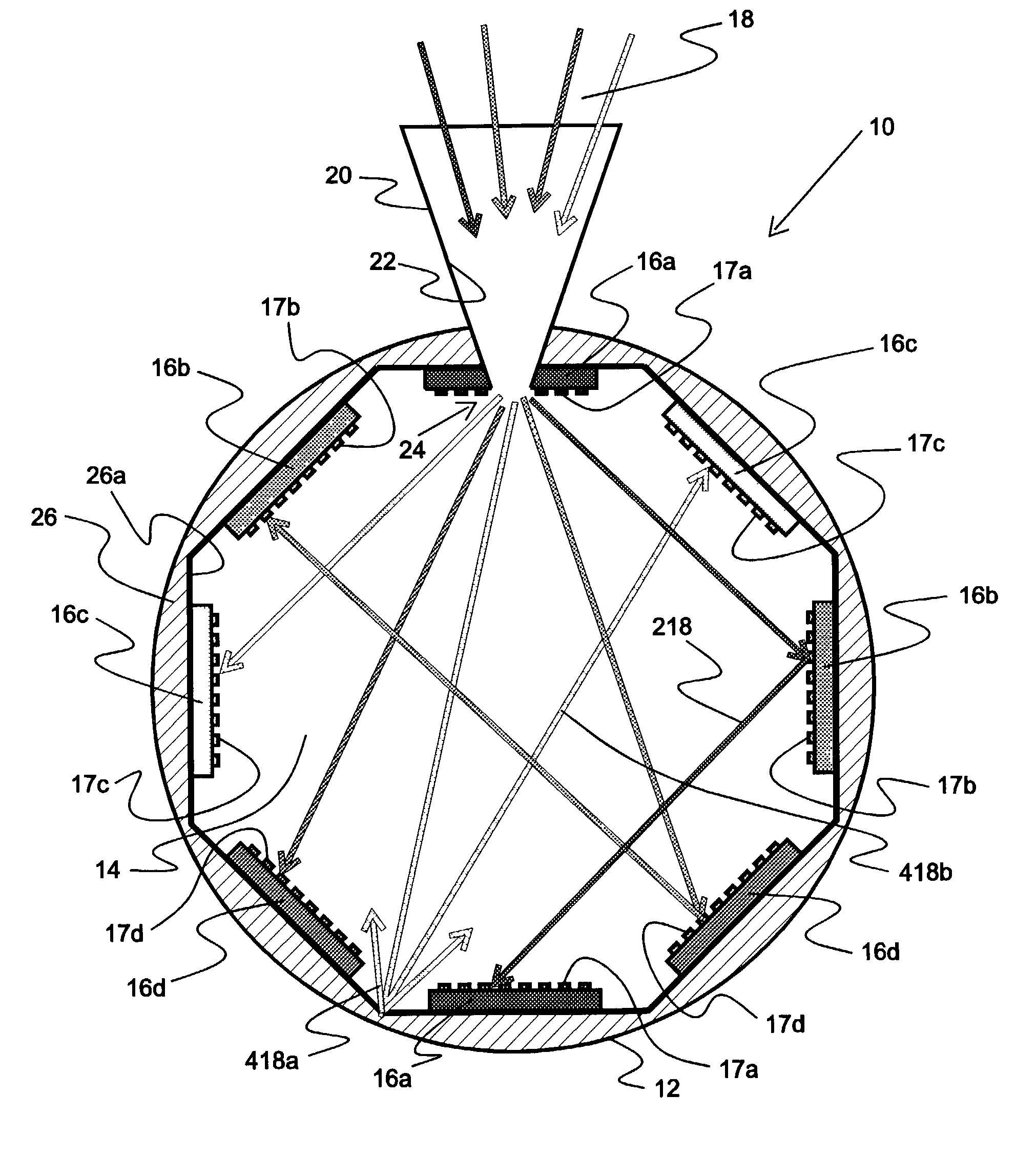
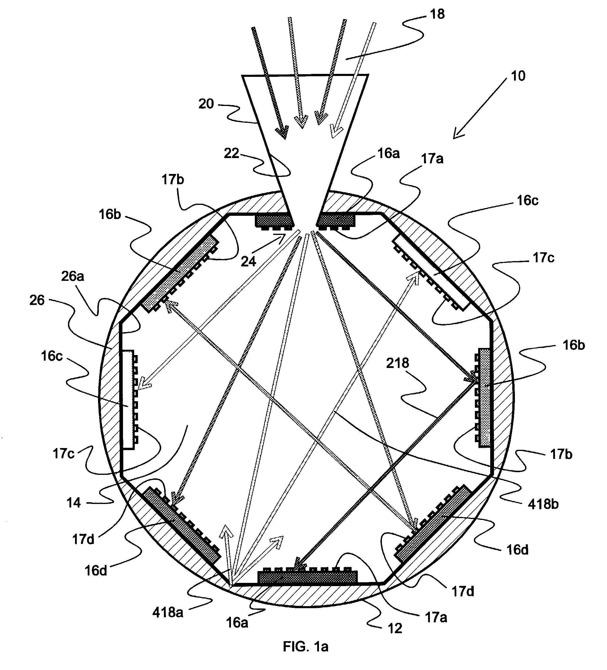
[0035] The invention herein is directed to the performance of a photovoltaic cavity converter (PVCC) module designed for a concentration in the range of 500 to over 1000 suns and a power output range of a few kilowatts to 50 KW.sub.e when combined with a primary dish and a secondary concentrator. A 1.5 KW prototype unit is presently being developed for use at the NREL High-Flux Solar Furnace (HFSF). The module herein is also expected to find use in, for example, DOE's Concentrating Solar Power (CSP) program to develop systems in the 1 to 5 kW.sub.e and 10 to 30 kW.sub.e size ranges based on reflective optics. A typical power range is about 30 to 50 kiloWatts. Connecting a plurality of such modules together in a power plant permits ...


PUM


Abstract

A concentrating photovoltaic module is provided which provides a concentration in the range of about 500 to over 1,000 suns and a power range of a few kW to 50 kW. A plurality of such modules may be combined to form a power plant capable of generating over several hundred megawatts. The concentrating photovoltaic module is based on a Photovoltaic Cavity Converter (PVCC) as an enabling technology for very high solar-to-electricity conversions. The use of a cavity containing a plurality of single junction solar cells of different energy bandgaps and simultaneous spectral splitting of the solar spectrum employs a lateral geometry in the spherical cavity (where the cell strings made of the single junction cells operate next to each other without mutual interference). The purpose of the cavity with a small aperture for the pre-focused solar radiation is to confine (trap) the photons so that they can be recycled effectively and used by the proper cells. Passive or active cooling mechanisms may be employed to cool the solar cells.

Description

[0001] The present invention is related generally to solar power, employing photovoltaic cells, and, more particularly, to novel concentrating photovoltaic modules that achieve extremely high efficiencies.[0002] State-of-the-art single junction solar arrays as well as concentrators using single junction solar cells utilize only a limited portion of the available solar spectrum, thereby wasting the remainder of available energy outside of their limited spectral response. The limitation is caused mainly by two basic "photon loss" mechanisms within the cells, namely, (1) loss by longer wavelengths and (2) loss by excess energy of photons. In the former case, photons with energy smaller than the "energy bandgap" or "forbidden gap" E.sub.g (direct bandgap semiconductor) or E.sub.g-E.sub.phonon (indirect bandgap semiconductors where E.sub.phonon is the phonon quantum of energy) cannot contribute to the creation of electron-hole pairs. In the latter case, in the spectrum range of interest,...

Claims


Application Information

Patent Timeline
IPC IPC(8): H01L31/00H01L31/052
CPCH01L31/052H01L31/0547Y02E10/52H01L31/0521H01L31/0549H02S40/44Y02E10/60
Inventor ORTABASI, UGUR
Owner UNITED INNOVATIONS
Why Eureka
Try Eureka