
Laser-written cladding for waveguide formations in glass

a technology of waveguide formation and laser writing, which is applied in the direction of photomechanical equipment, instruments, manufacturing tools, etc., can solve the problems of limiting the minimum radius of curvature and the self-limiting of desired localized increases in refractive index, so as to improve contrast and reduce the effect of refractive index

Inactive Publication Date: 2003-11-20
CORNING INC
View PDF25 Cites 23 Cited by
  • Summary
  • Abstract
  • Description
  • Claims
  • Application Information

AI Technical Summary

Benefits of technology

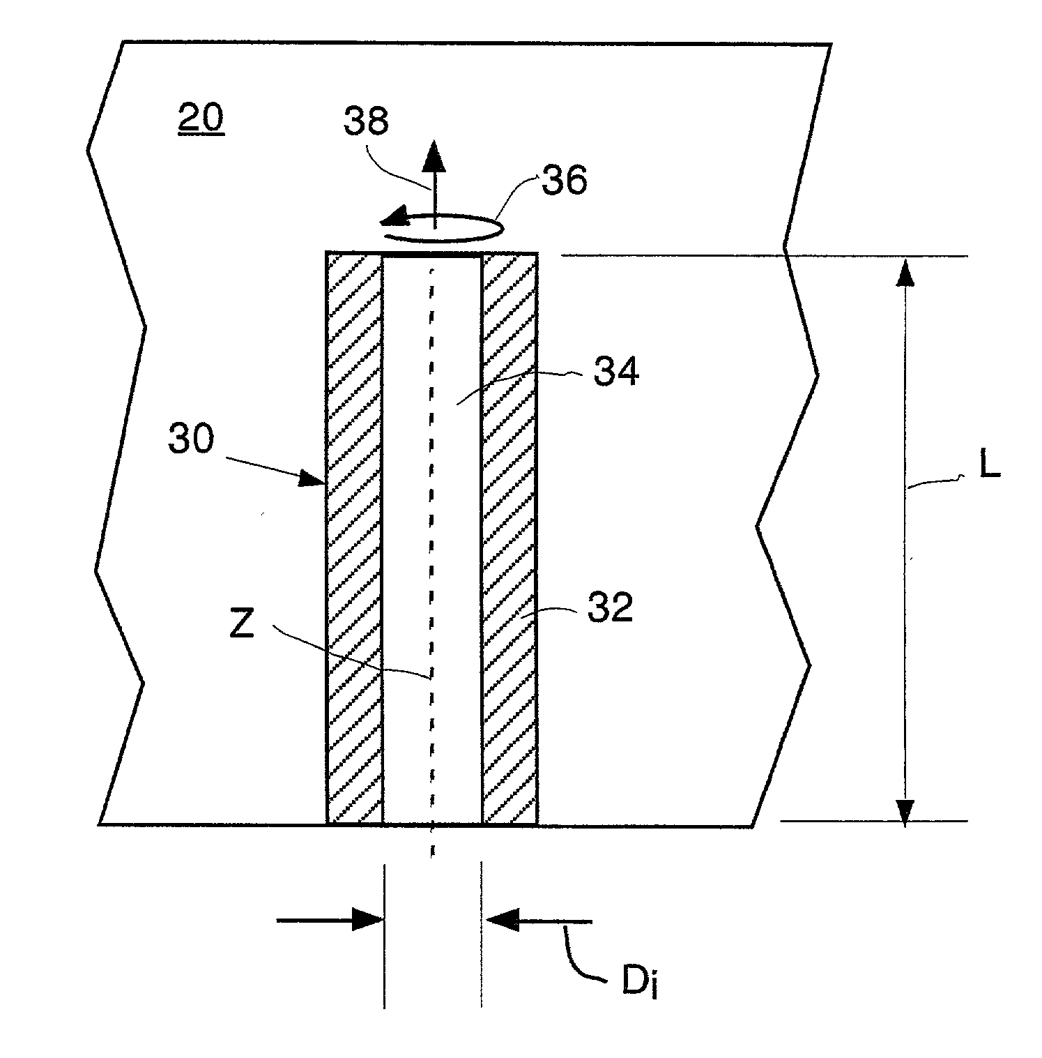
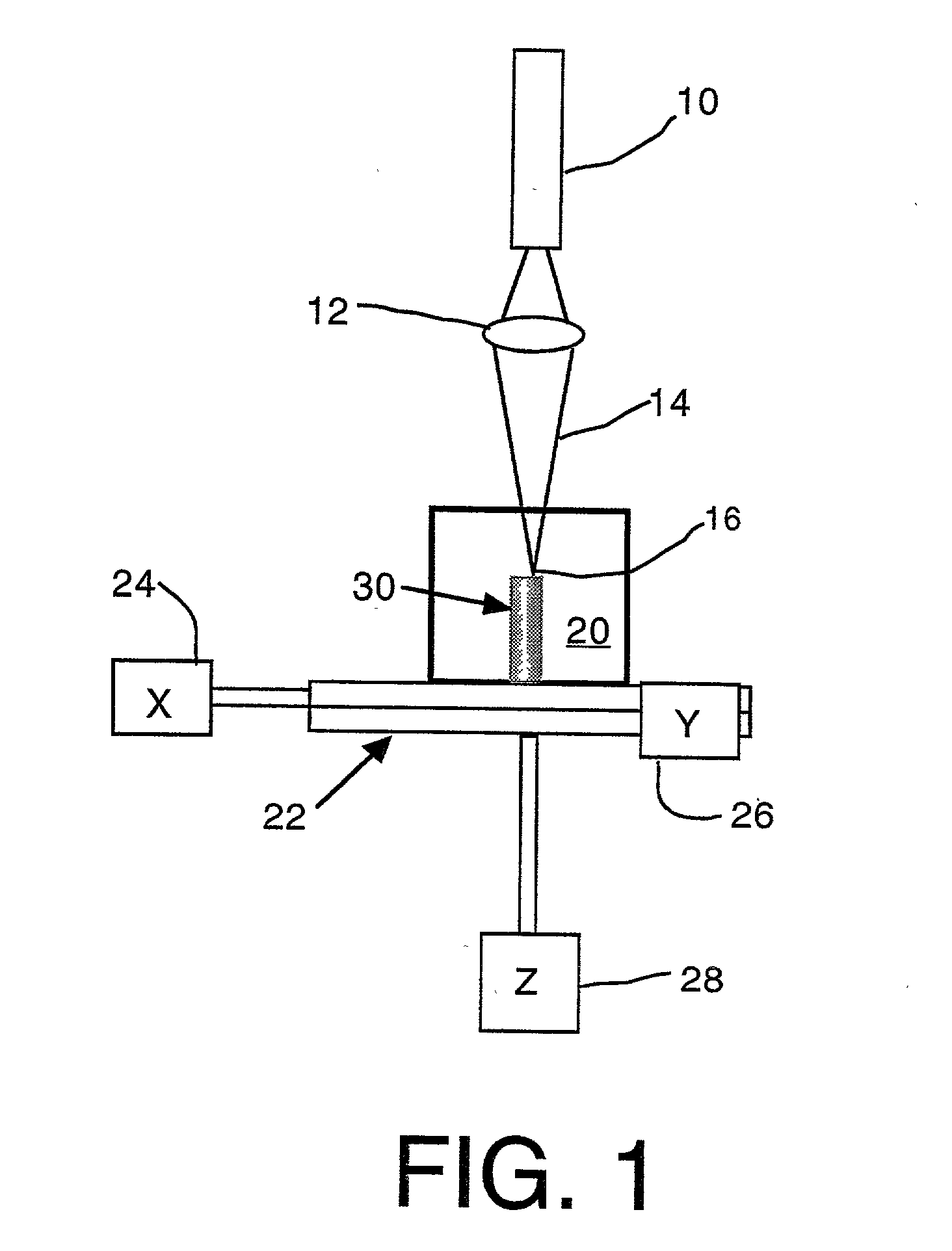
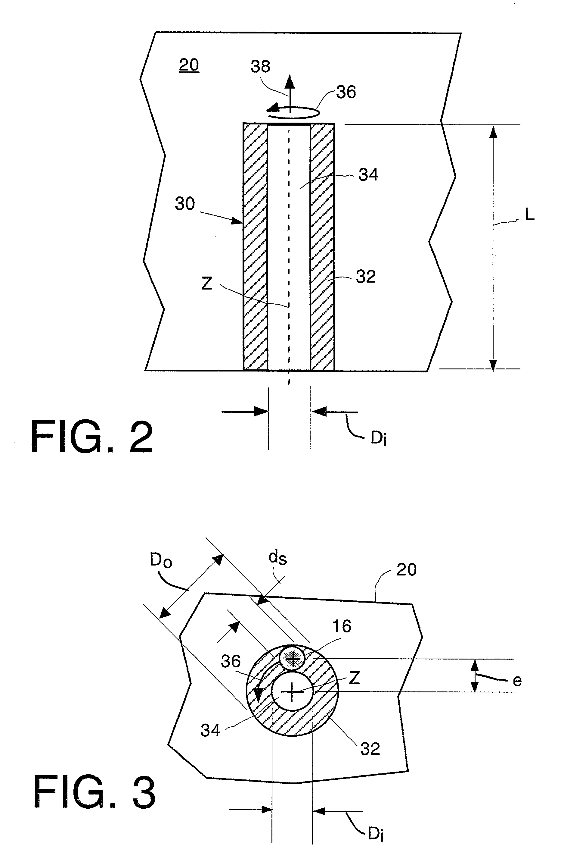
[0008] Our invention in one or more preferred embodiments provides for directly writing embedded waveguides with improved contrast between core and cladding portions by using high-energy pulses to produce contrasting index cladding. Pulse energies beyond the range at which non-linear absorption mechanisms produce slight increases in refractive index are used in accordance with our invention to reverse the index effect and produce more significant decreases in refractive index. Such refractive index decreases are patterned within the interiors of optical media to produce the cladding of waveguides. Although associated with possible structural changes, such as the formation of voids, the significantly reduced cladding index supports strong light-guiding properties along remaining unmodified cores.
[0009] Producing waveguides within the interior of an optical medium by writing a surrounding cladding portion of the embedded waveguides has several advantages over writing a core portion of the embedded waveguides. Unlike writing regimes focused on the core, corresponding writing regimes focused on the cladding do not subject the core to changes that could significantly reduce the core's ability to transmit light efficiently. In addition, much more significant index contrasts between the core and cladding are made possible by using high-energy pulses to lower the index of the cladding. The remaining core can be sized in diameter and shaped as desired for conveying and orienting signals and can be tapered as a function of length as desired for coupling or other purposes.

Problems solved by technology

However, in both instances, the desired localized increases in refractive index tend to be self-limiting in the range of a multiple of 10.sup.-3.
Bending losses associated with such weak waveguiding properties limit the minimum radius of curvature through which the waveguides can be bent during use.

Method used


Image

  • Laser-written cladding for waveguide formations in glass
  • Laser-written cladding for waveguide formations in glass
  • Laser-written cladding for waveguide formations in glass

Examples


example 2

[0038] A similar amplifier laser is used to write a waveguide in an alternative single-crystal optical medium made of calcium fluoride (CaF.sub.2). The wavelength, pulse width, and repetition rate of the laser are the same as in Example 1, but the pulse energy is much lower. The focusing is provided by a 10.times.0.26 numerical aperture (NA) objective. Helical tracks are written along one of the crystal axes at an eccentric offset of 8 microns (.mu.m), a thread step of 3 microns (.mu.m), and a writing speed of 100 microns per second (.mu.m / s). A distinctive cladding portion circumscribing a remaining core portion is obtained at pulse energies of 0.5 microjoules (.mu.J).

[0039] At higher pulse energies (e.g., 20 .mu.J), control over the index profile of the waveguides is expected to be reduced. However, at somewhat lower pulse energies (e.g., 0.3 .mu.J), reductions in refractive index are still expected to be writeable into the calcium fluoride (CaF.sub.2). Below such an exposure thre...


PUM

PropertyMeasurementUnit
Timeaaaaaaaaaa
Timeaaaaaaaaaa
Diameteraaaaaaaaaa

Abstract

High-energy pulses of femtosecond lasers form cladding portions of waveguides in bulk glass by producing localized reductions in refractive index. The cladding portions written by the high-energy pulses circumscribe unexposed core portions for defining light-guiding pathways in the bulk glass.

Description

[0001] Embedded waveguides can be written by focusing high-energy pulses inside glass. Wavelengths of the pulses are beyond the normal absorption edge of the glass so that the pulses can transmit through the glass without appreciably altering the glass structure until a threshold power density is reached. Refractive index changes induced at the threshold power densities contrast with unaltered portions of the glass to provide light-guiding properties.[0002] The writing of optical waveguides (i.e., light-guiding or light-managing structures) embedded within glass is accomplished by focusing high energy pulses within the glass and relatively translating the pulses with respect to the glass. The high-energy pulses have wavelengths beyond the absorption edge (optical density of unity) of the glass, but are focused to power densities within the glass at which the glass undergoes a change in refractive index. Thus, the pulses can penetrate the glass without dispersing their energy or dama...

Claims


Application Information

Patent Timeline
IPC IPC(8): B23K26/00C03C23/00G02B6/13
CPCC03C23/0025Y10S430/146G02B6/13
Inventor SCHROEDER, JOSEPH F.STRELTSOV, ALEXANDER
Owner CORNING INC
Learn More