

Recoverable ground source heat pump
a ground source heat pump and heat sink technology, applied in heat pumps, domestic cooling devices, lighting and heating devices, etc., can solve the problems of limiting the overall cost effectiveness limiting the application of ground source heat pumps for buildings without a large open space, and high initial cos
Inactive Publication Date: 2003-12-04
XU YUNSHENG
View PDF0 Cites 53 Cited by
- Summary
- Abstract
- Description
- Claims
- Application Information
AI Technical Summary
Problems solved by technology
(1) The underground heat exchange system requires extensive drilling and / or trenching plus a significant amount of pipe loop material. This results in a higher initial cost. The loop system must be large enough to provide sufficient heat transfer efficiency and energy storage capacity to ensure an acceptable temperature elevation of the ground medium during the entire summer season (cooling) and winter season (heating). This limits greatly the overall cost effectiveness of ground source heat pumps.
(2) For the same reason, in order to keep the temperature change of the ground medium to a moderate level after a season's heat injection or heat abstraction, there must be sufficient ground space to build a large heat exchange system. This greatly restricts the application of ground source heat pumps for buildings without a large open space, especially for multi-story and high-rise buildings.
(3) Because of the need to limit initial cost and to apply the system to buildings with small open space, there is a greater risk that the system will under perform. This poor performance could manifest as higher energy consumption and / or insufficient heating / cooling output due to the temperature being too high in the cooling fluid out of the ground heat exchange system in the cooling mode, or too low in the heating fluid in the heating mode. This risk is significantly increased when there is insufficient site information, poor understanding of local geological conditions, or little design experience. To retroactively correct such a poor performing system requires significant additional cost.
(4) The worst situations of poor design includes freezing of the circulation fluid, which can be caused by continuous heat extraction from the ground. In order to minimize this risk, antifreeze solution is generally used in most pipe loops in northern locations where the system operates primarily in the heating domain. Use of antifreeze solution causes one or more of the following problems: (a) environmental pollution, (b) increased health and safety risk, (c) corrosion of equipment, and (d) increase the initial cost.
(1) Similar to the ground source heat pump, the ice storage system is also always associated with a larger additional cost. There has been much effort to develop a cheaper storage medium and a cheaper mechanical system. However, the additional cost is still significant.
(2) The storage medium must be cooled to a temperature below its freezing point in order to use the latent heat capacity of the medium released and absorbed during phase change. Cooling the storage medium to an unnecessarily low level is not efficient from the energy saving point of view.
(3) Low temperature of the storage medium (for instance, 0.degree. C. for water) will release low temperature cold air to the building in the day time. The low temperature air supply may cause water to condense on the surface of duct work and terminal units (diffusers, fan / coil units). Special effort must be made to prevent damage from the moisture and condensation to the building wall and ceiling.
(4) Most energy storage systems are designed only for space cooling but not for heating. For example, the ice-ball storage system may be able to extract sufficient energy from water-to-ice phase change to store "cold", but the heat storage in the same volume of water is far less from the energy needed for heating of the building space.
Method used
View moreImage
Smart ImageViewing Examples

Examples
embodiment
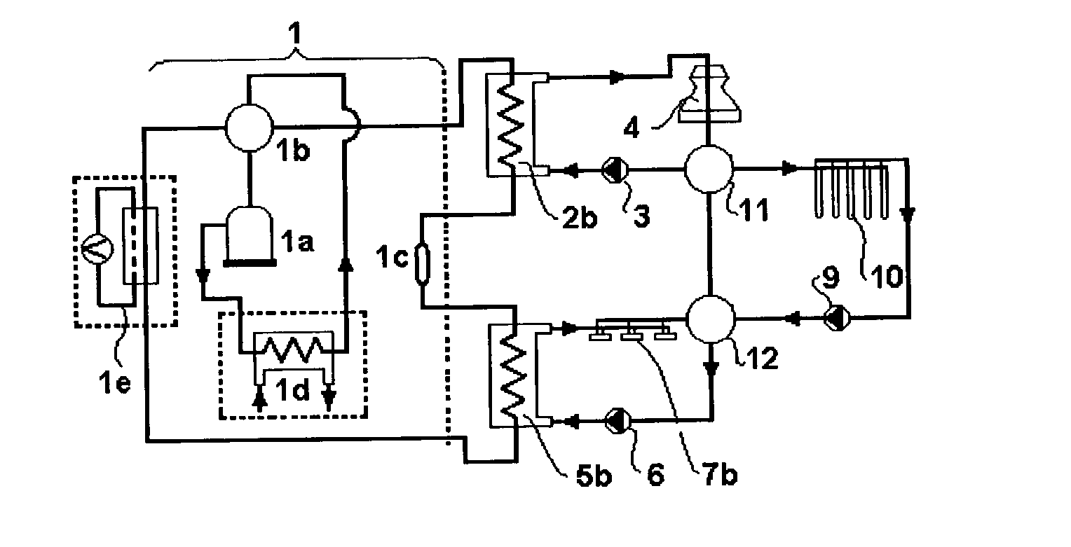
DESCRIPTION--FIG. 6--ALTERNATIVE EMBODIMENT
[0089] FIG. 6. shows an alternative looping of the heat pump system with two forced air-to-fluid heat exchangers used as in-door and out-door heat transfer equipment.
[0090] In this application, the system is simplified to use only two heat exchangers, out-door heat exchanger 2b and in-door heat exchanger 5a. Heat exchanger 2b has to be fluid-to-fluid type and connected to ground loops 10. The in-door heat transfer equipment 7a must be an air-to-fluid heat exchanger. The duct work attached to the heat exchanger 7a is divided into to directions. A reversing valve 13 is installed to change the direction of the forced air to in-door or out door space.
Login to View More PUM
 Abstract
Recoverable Ground Source Heat Pump system with energy storage function which uses and stores off-peak-hours electricity to maintain the ground medium temperature to ensure the efficient operation of the system during on-peak electricity hours. The release and receiving of energy is accomplished through the ground heat exchanger by flowing the fluid through different routings of the circulation loop using reversing vales. Space heating and cooling is assured while the underground medium temperature is recovered. The heat pump system of the invention has less initial investment compared to conventional ground source heat pump and ice energy storage cooling systems; requires less ground space; provide operating energy cost savings; assures performance of operation; and avoids using antifreeze solution in the ground circulation fluid that may cause environmental, safety and erosion problems.
Description
[0001] This invention uses the transmission of my pending application in foreign country (China), application number: 01118555.4 filed Jun. 1, 2001.BACKGROUND--FIELD OF INVENTION[0002] This invention relates to heat pump for heating and cooling, specifically to such heat pump with ground source.BACKGROUND--DESCRIPTION OF PRIOR ART[0003] Ground Source Heat Pump System[0004] Ground source heat pump uses ground soil, sand, rock, and / or water as a medium to provide energy for heating in winter. A minor energy input can produce 3-5 times as much heating energy in the winter through subtracting thermal energy from the ground. In the summer, the ground medium is used as a "heat sink" to receive the heat dissipation from the refrigeration device. Due to its great savings in operational costs in comparison with conventional heating and cooling devices, ground source heat pump has been used more and more for heating and cooling, but nevertheless all the closed loop heat pump system using grou...
Claims
Login to View More Application Information
Patent Timeline
 Patent Type & AuthorityApplications(United States)
IPC IPC(8): F25B13/00F25B25/00F25B30/06F25B40/04
CPCF25B13/00F25B25/005F25B30/06F25B40/04F25B2400/24F25B2313/004F25B2313/008F25B2313/02541F25B2313/02543F25B2313/002
InventorXU, YUNSHENG
OwnerXU YUNSHENG