Driving apparatus of a linear motor

a technology of linear motors and driving apparatuses, which is applied in the direction of motor/generator/converter stoppers, piston pumps, dynamo-electric converter control, etc., can solve the problems of increasing the cost, the fluctuation of the refrigerating capacity of the compressor, and the inability to determine the resonance frequency of the linear compressor

Active Publication Date: 2004-01-08
PANASONIC CORP
View PDF2 Cites 120 Cited by
  • Summary
  • Abstract
  • Description
  • Claims
  • Application Information

AI Technical Summary

Problems solved by technology

However, the elasticity caused by compressed gas varies significantly depending on load fluctuations, and thus the resonant frequency of the linear compressor cannot be determined uniquely.
Firstly, in the process of the driving frequency nearing the resonant frequency, the amplitude of the piston (movable element) increases largely, and in a compressor of a large resonance factor, collision of piston and cylinder head may occur, or the refrigerating capacity of the compressor may fluctuate significantly. In particular, in an environment of vibration applied from outside of a vehicle or the like, the amplitude of the piston resonates at its resonant frequency, and such problem occurs.
Secondly, in this method, displacement of the piston in the cylinder must be measured, and therefore a displacement sensor must be incorporated in the linear compressor, and the volume and weight of the compressor are increased by the portion of the sensor. Still more, to calculate the speed by differentiating the signal from the displacement sensor, or to calculate the phase difference of speed and current, a relative complicated control device such as microcomputer or MPU (microprocessing unit) is needed, and thus the cost is increased.
Thirdly, when using the displacement sensor, the displacement sensor must be sealed in a shell of the linear compressor. Thus it is required to guarantee the operation reliability of the displacement sensor in severe working conditions including temperature, pressure, and refrigerant-resistance.

Method used


Image

  • Driving apparatus of a linear motor
  • Driving apparatus of a linear motor
  • Driving apparatus of a linear motor

Examples


first embodiment

[0057] First Embodiment

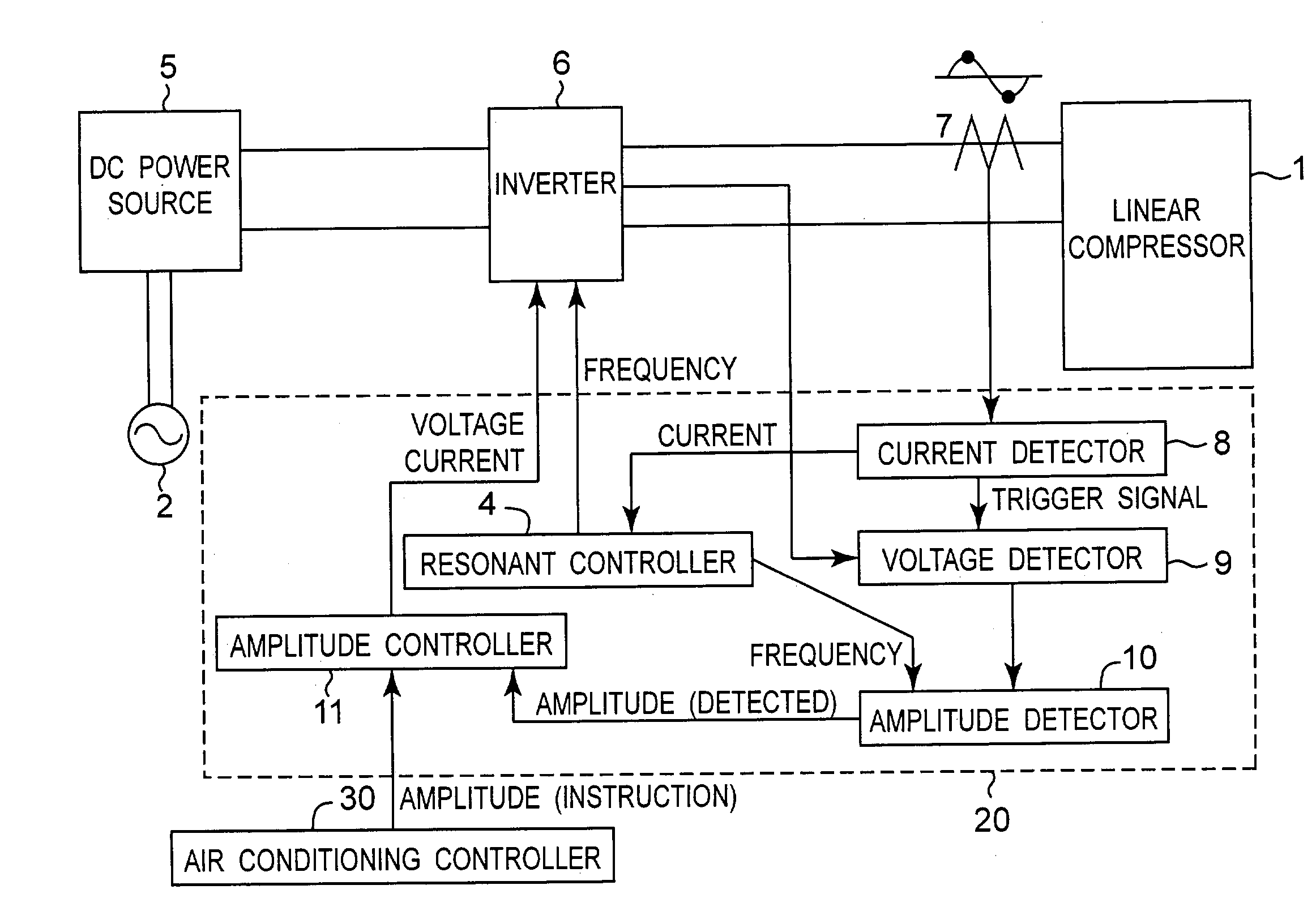
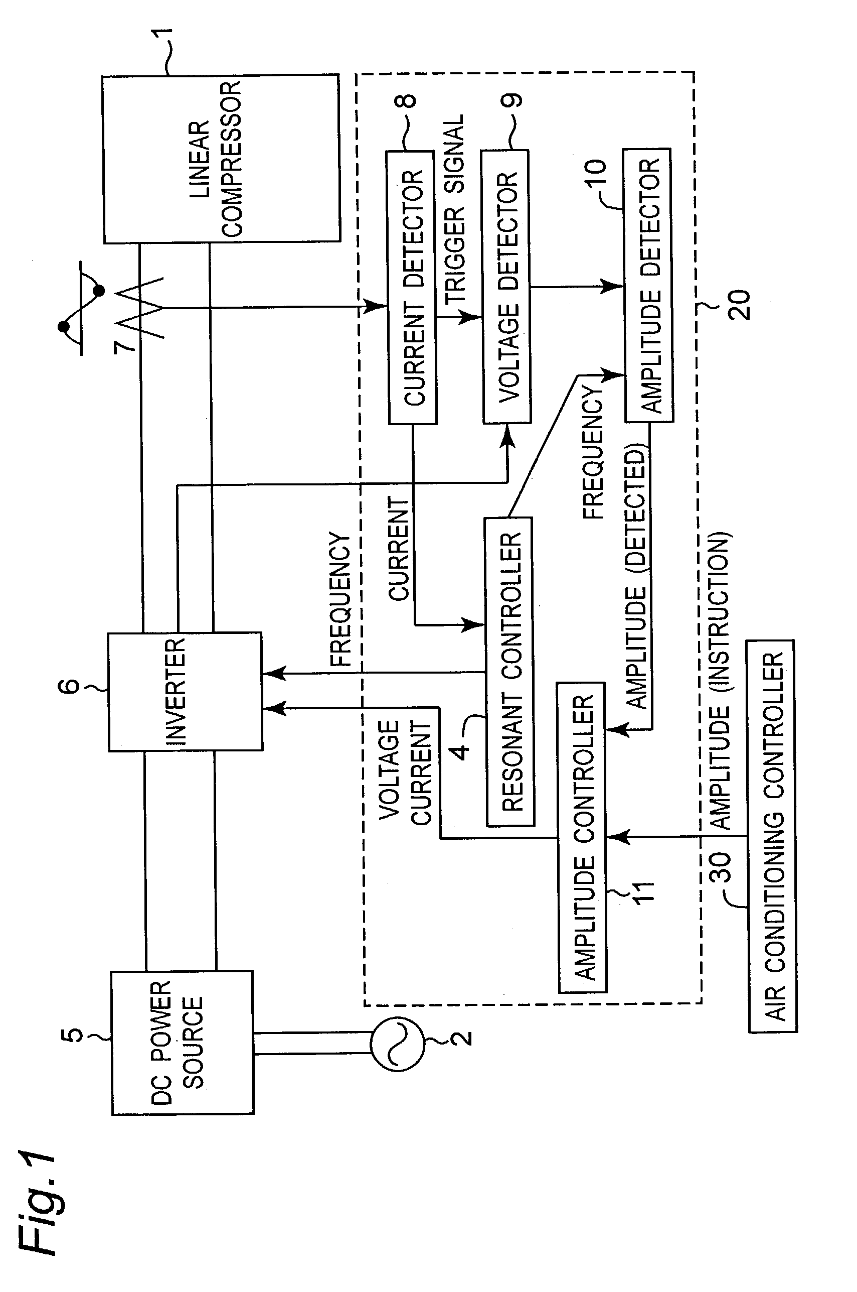
[0058] FIG. 1 is a block diagram showing a configuration of a driving apparatus of a linear compressor in the first embodiment of the invention. As shown in the diagram, the driving apparatus includes a DC power source 5 which generates a DC voltage from an AC power source 2, an inverter 6 which produces a driving voltage for a linear compressor 1, and a controller 20 which controls the inverter 6. The controller 20 contains a resonant controller 4, a current detector 8, a voltage detector 9, an amplitude detector 10, and an amplitude controller 11. The controller 20 receives an amplitude instruction from an air conditioning controller 30 for obtaining a capacity of the linear compressor 1 necessary for realizing a desired air conditioning control.

[0059] The DC power source 5 serves as supplying a DC voltage to the inverter 6, and generally includes a commercial AC power source 2, a diode bridge for rectifying the AC power, and a smoothing capacitor.

[0060] The...

second embodiment

[0090] Second Embodiment

[0091] FIG. 5 is a block diagram showing a configuration of a driving apparatus of a linear compressor according to the second embodiment of the invention. As shown in the figure, the driving apparatus includes a DC power source 5 for generating a DC voltage from an AC power source 2, an inverter 6 for producing a driving voltage for a linear compressor 1, and a controller 22 for controlling the inverter 6. The controller 22 contains a resonant controller 4, a current detector 8, a voltage detector 9, an amplitude detector 10, an output controller 12, and an output controller 13.

[0092] The current detector 8, voltage detector 9, and amplitude detector 10 are the same as in the first embodiment.

[0093] The output detector 12 detects the output of the linear motor of the linear compressor 1. Specifically, the motor output is calculated in formula (6) from the amplitude detected by the amplitude detector 10, the driving frequency, and piston mass which is know in...


PUM


Abstract

A driving apparatus of a linear motor which reciprocally drives a movable element supported by an elastic member, includes an inverter that converts a direct current power into an alternating-current power with a specified frequency to drive the linear motor, a current detector that detects the output current of the inverter, a voltage detector that detects the output voltage of the inverter, an amplitude detector that detects an amplitude of the movable element of the linear motor, an amplitude controller adjusts the output current or output voltage in a first control cycle so that the amplitude of the movable element is a desired constant value, and a resonant controller that adjusts the output frequency of the inverter in a second control cycle which is larger than the first control cycle so that the output current of the inverter is substantially minimum on condition that the amplitude is substantially constant.

Description

[0001] 1. Technical Field of the Invention[0002] The present invention relates to a driving apparatus of a resonance type linear motor for driving a movable element supported by an elastic member using a reciprocal motor (linear motor).[0003] 2. Related Art[0004] Hitherto, as the device using a resonance type linear motor, for example, a linear compressor for air conditioner is known. The linear compressor is designed to generate compressed gas, by making use of a mechanical elastic member or elasticity of compressed gas and linear motor.[0005] Referring to FIG. 13, a structure of linear compressor using a spring as elastic member is detailed. A piston 61 is movably supported on a cylinder 60 along its axial direction. A magnet 62 is fixed to the piston 61. A stator coil 64 buried in an outer yoke 63 is disposed at a position facing the magnet 62. A compression chamber 65 formed of the cylinder 60 and piston 61 is connected to a suction pipe 66 and a discharge pipe 67. The suction p...

Claims


Application Information

Patent Timeline
Patent Type & Authority Applications(United States)
IPC IPC(8): F04B49/06F04B35/04H02K33/04H02P25/02H02P25/06
CPCF04B35/045F04B2203/0401H02P25/027F04B2203/0404H02K33/04F04B2203/0402H02P25/032H02P25/00H02P27/06
Inventor YOSHIDA, MAKOTOUEDA, MITSUO
Owner PANASONIC CORP
Why Eureka
Try Eureka