Imaging device and digital camera using the imaging device

a technology of imaging device and lens barrel, which is applied in the direction of camera filters, instruments, television systems, etc., can solve the problems of insufficient security of peripheral light, inability to secure the optical performance of image sensors, and difficulty in setting the pupil of the microlens, so as to reduce the cost of imaging devices, improve the degree of freedom of lens barrel structure, and thin optical systems

Inactive Publication Date: 2004-01-15
MINOLTA CO LTD
View PDF3 Cites 197 Cited by
  • Summary
  • Abstract
  • Description
  • Claims
  • Application Information

AI Technical Summary

Benefits of technology

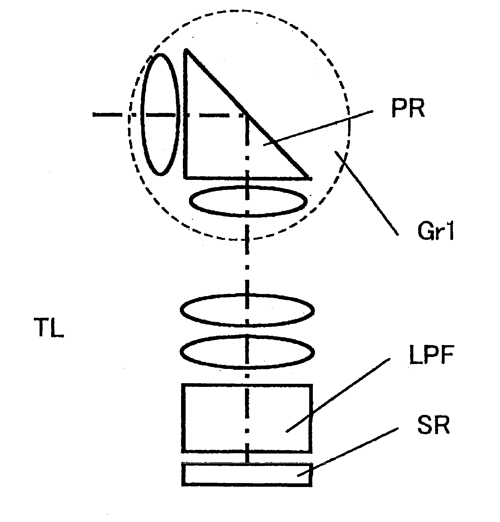
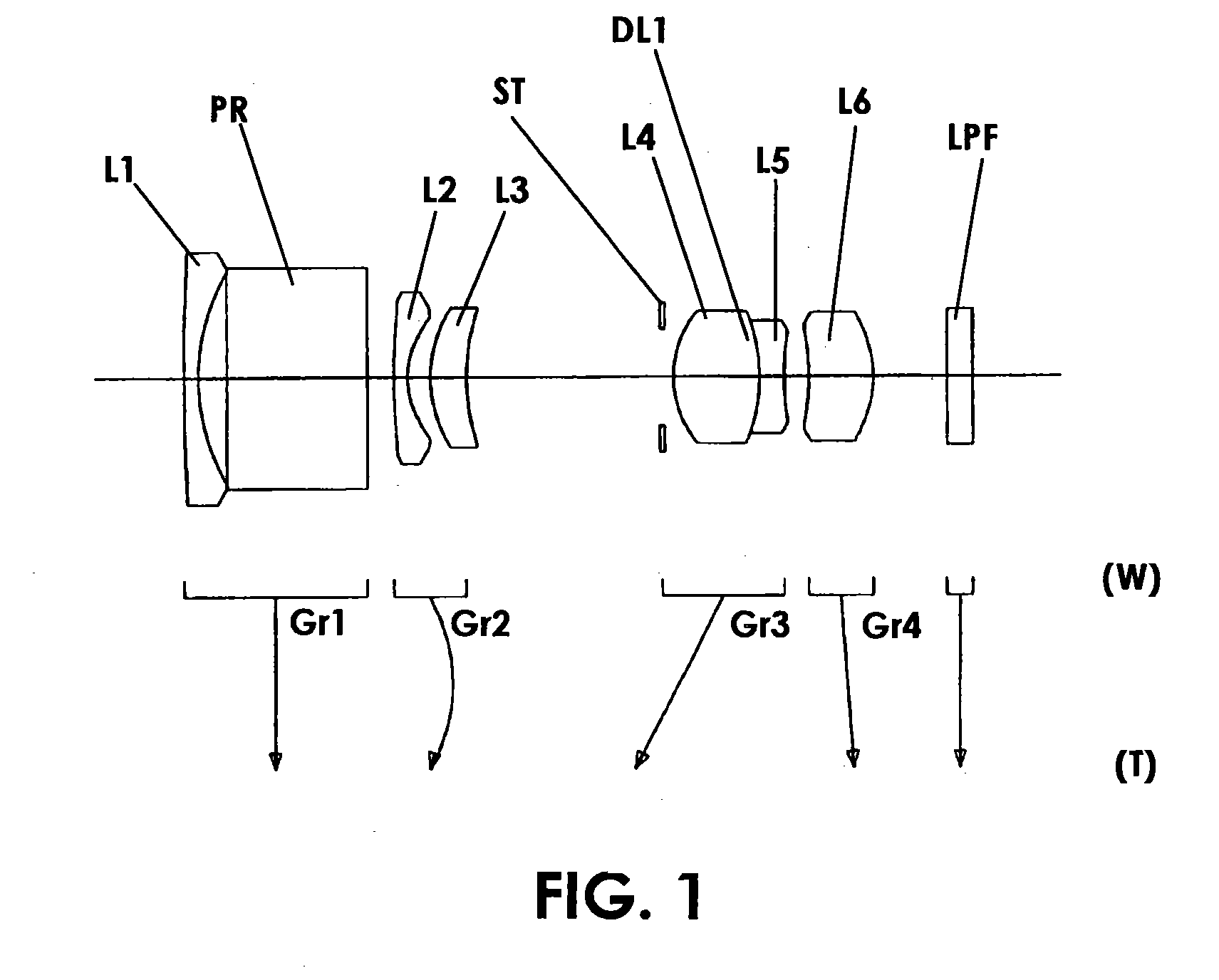
0060] It is desirable that not more than two lens elements be disposed on the object side of the reflecting surface. In a structure having in the first lens unit the prism PR having a reflecting surface that bends the optical axis of the object light substantially 90 degrees, the thickness of the optical system substantially depends on the distance from the object side surface of the lens element disposed on the most object side to the reflecting surface. Therefore, by disposing not more than two lens elements on the object side of the reflecting surface, a thin optical system can be obtained. In particular, when the first lens unit Gr1 includes only one lens element and the reflecting surface, the degree of freedom of the lens barrel structure can be increased, so that cost reduction of the imaging device can be attained. When the first lens unit Gr1 includes only two lens elements and the reflecting surface, relative decentration aberration correction can be performed, which is advantageous in optical perfo

Problems solved by technology

However, in these zoom lens systems, since the exit pupil of the lens system in the shortest focal length condition is situated comparatively near the image plane, it does not match with the pupil of the microlens provided so as to correspond to each pixel of the image sensor having high pixels, so that a sufficient quantity of peripheral light cannot be secured.
In addition, since the position of the exit pupil largely varies during zooming, the setting of the pupil of the microlens is difficult.
Further, since requ

Method used


Image

  • Imaging device and digital camera using the imaging device
  • Imaging device and digital camera using the imaging device
  • Imaging device and digital camera using the imaging device

Examples


example 2

[0089]

2 f = 4.5 - 7.9 - 12.9 Fno. = 2.0 - 2.85 - 3.74 [Radius of [Axial [Refractive [Abbe Curvature] Distance] Index(Nd)] Number(vd)] r1 = 33.725 d1 = 0.800 N1 = 1.85000 v1 = 40.04 r2 = 11.351 d2 = 1.200 r3 = 25.554 d3 = 1.458 N2 = 1.75450 v2 = 51.57 r4 = 37.693 d4 = 0.800 r5 = .infin. d5 = 8.200 N3 = 1.84666 v3 = 23.82 r6 = .infin. d6 = 1.500 - 3.420 - 1.500 r7 = 97.822 d7 = 0.800 N4 = 1.52510 v4 = 56.38 r8* = 5.111 d8 = 0.743 r9 = 6.467 d9 = 2.000 N5 = 1.84666 v5 = 23.82 r10 = 10.975 d10 = 10.550 - 4.249 - 1.028 r11 = .infin. d11 = 0.650 r12 = 6.194 d12 = 5.604 N6 = 1.75450 v6 = 51.57 r13 = -6.781 d13 = 0.010 N7 = 1.51400 v7 = 42.83 r14 = -6.781 d14 = 1.183 N8 = 1.84666 v8 = 23.82 r15* = 38.043 d15 = 3.186 - 8.555 - 13.974 r16* = 16.667 d16 = 3.812 N9 = 1.77250 v9 = 49.77 r17* = -5.893 d17 = 2.712 - 1.724 - 1.447 r18 = .infin. d18 = 1.500 N10 = 1.51680 v10 = 64.20 r19 =.infin. [Aspherical Coefficient] r8* .epsilon. = 0.10000000E+01 A4 = -0.15428275E-03 A6 = -0.42877249E-04 A8 = 0....

example 3

[0090]

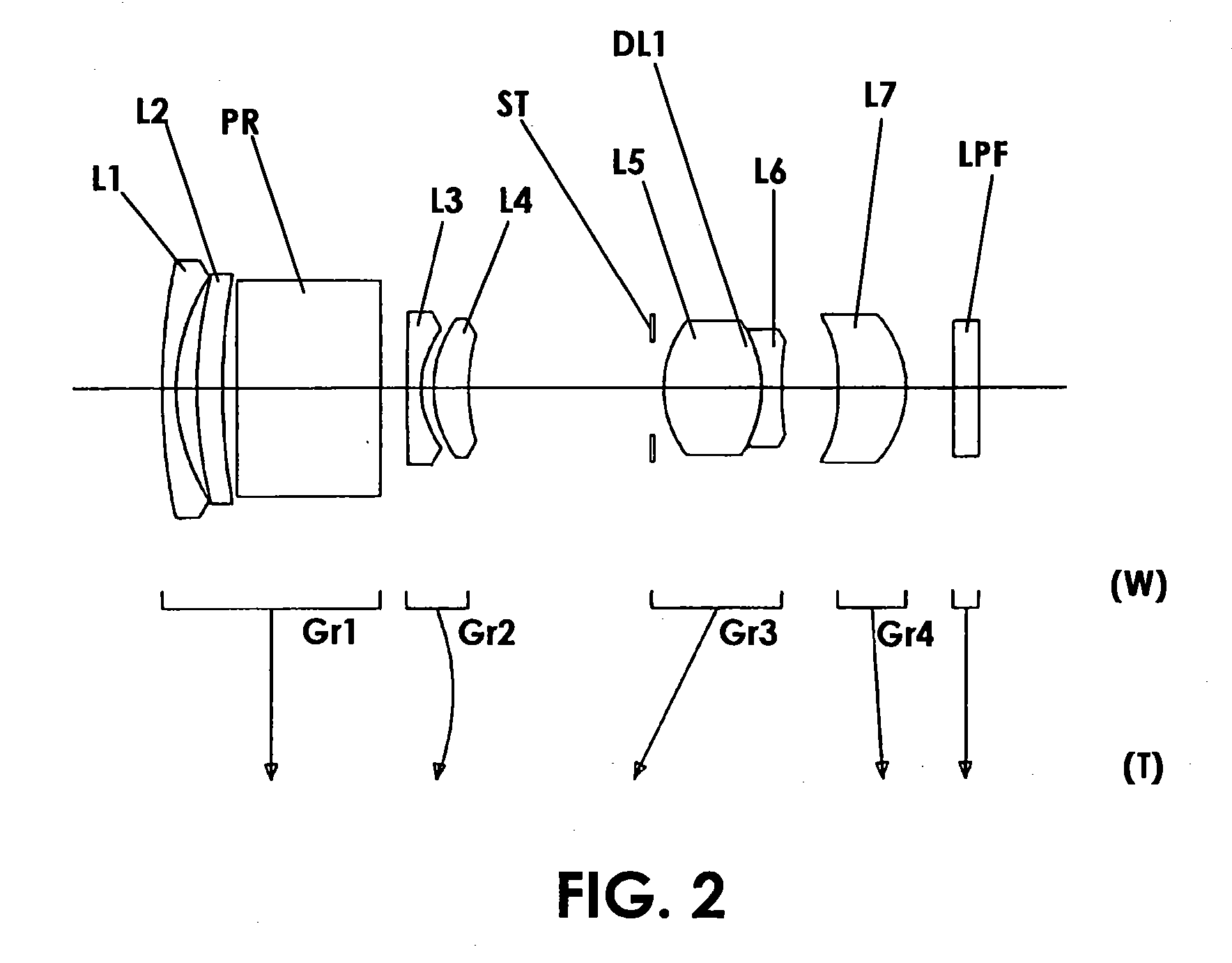
3 f = 4.5 - 7.9 - 12.9 Fno. = 2.0 - 2.81 - 3.67 [Radius [Axial [Refractive [Abbe of Curvature] Distance] Index(Nd)] Number(vd)] r1 = 15.797 d1 = 0.800 N1 = 1.58913 v1 = 61.11 r2 = 7.557 d2 = 2.700 r3 = .infin. d3 = 8.009 N2 = 1.84666 v2 = 23.82 r4 = .infin. d4 = 1.500 - 3.160 -1.500 r5 = -26.368 d5 = 0.800 N3 = 1.48749 v3 = 70.44 r6* = 4.708 d6 = 0.518 r7 = 5.361 d7 = 2.154 N4 = 1.85000 v4 = 40.04 r8* = 10.802 d8 = 11.235 - 4.910 - 1.331 r9 = .infin. d9 = 0.650 r10 = 6.699 d10 = 4.000 N5 = 1.75450 v5 = 51.57 r11 = -9.744 d11 = 0.010 N6 = 1.51400 v6 = 42.83 r12 = -9.744 d12 = 0.800 N7 = 1.79850 v7 = 22.60 r13 = 67.530 d13 = 0.537 r14 = 28.497 d14 = 0.800 N8 = 1.58340 v8 = 30.23 r15* = 18.947 d15 = 2.612 - 8.560 - 14.167 r16* = - 30.752 d16 = 4.200 N9 = 1.52510 v9 = 56.38 r17* = -5.241] d17 = 2.934 - 1.651 - 1.283 r18 = .infin. d18 = 1.500 N10 = 1.51680 v10 = 64.20 r19 = .infin. [Aspherical Coefficient] r6* .epsilon. = 0.10000000E+01 A4 = -0.10145481E-02 A6 = -0.72075706E-04 A8 ...

example 4

[0091]

4 f = 4.5 - 7.9 - 12.9 Fno. = 2.0 - 2.88 - 3.77 [Radius [Axial [Refractive [Abbe of Curvature] Distance] Index(Nd)] Number(vd)] r1 = 24.847 d1 = 0.800 N1 = 1.85026 v1 = 32.15 r2 = 9.507 d2 = 1.200 r3* = 18.529 d3 = 1.878 N2 = 1.52200 v2 = 52.20 r4 = 37.877 d4 = 0.800 r5 = .infin. d5 = 8.200 N3 = 1.84666 v3 = 23.82 r6 = .infin. d6 = 1.500 - 3.255 - 1.500 r7= -23.840 d7 = 0.800 N4 = 1.52200 v4 = 52.20 r8* = 5.612 d8 = 0.500 r9* = 6.897 d9 = 2.300 N5 = 1.84666 v5 = 23.82 r10* = 17.332 d10 = 11.012 - 4.659 - 1.072 r11 = .infin. d11 = 0.650 r12 = 6.160 d12 = 6.000 N6 = 1.75450 v6 = 51.57 r13 = -6.615 d13 = 0.010 N7 = 1.51400 v7 = 42.83 r14 = -6.615 d14 = 0.969 N8 = 1.84666 v8 = 23.82 r15* = 29.536 d15 = 1.496 - 7.489 - 12.982 r16* = -31.130 d16 = 4.200 N9 = 1.52510 v9 = 56.38 r17* = 5.934 d17 = 3.226 - 1.831 -1.680 r18 = .infin. d18 = 1.500 N10 = 1.51680 v10 = 64.20 r19 = .infin. [Aspherical Coefficient] r3* .epsilon. = 0.10000000E+01 A4 = 0.11455958E-03 A6 = -0.33371789E-06 A8 = 0...


PUM


Abstract

An imaging device has a zoom lens system having a plurality of lens units and forming an optical image of an object so as to continuously optically zoom by varying distances between the lens unit; and an image sensor converting the optical image formed by the zoom lens system to an electric signal. The zoom lens system has from an object side, a first lens unit being overall negative and including a reflecting surface that bends a luminous flux substantially 90 degrees; and a second lens unit disposed with a variable air distance from the first lens unit, and having an optical power, and wherein at least one lens element made of resin is included in the entire lens system.

Description

[0001] This application is based on application No. 2002-196168 filed in Japan on Jul. 4, 2002, the content of which is hereby incorporated by reference.[0002] The present invention relates to an imaging device having an image sensor that converts, to electric signals, optical images formed on the light receiving surface of a charge coupled device (CCD), a complementary metal-oxide semiconductor (CMOS) sensor or the like, and more particularly, to an imaging device which is a principal element of cameras incorporated in or externally attached to digital cameras, personal computers, mobile computers, mobile telephones, personal digital assistances (PDAs) and the like. Specifically, the present invention relates to a compact imaging device having a zoom lens system.DESCRIPTION OF THE PRIOR ART[0003] In recent years, digital cameras have been rapidly becoming widespread that convert an optical image to electronic signals by using an image sensor such as a CCD or a CMOS sensor instead o...

Claims


Application Information

Patent Timeline
IPC IPC(8): G03B11/00G02B15/177G02B15/20H04N5/225H04N101/00
CPCH04N5/2254G02B15/177G02B15/142G02B15/1455G02B15/1445
Inventor HAGIMORI, HITOSHIYAMAMOTO, YASUSHIYAGYU, GENTAISHIMARU, KAZUHIKO
Owner MINOLTA CO LTD
Why Eureka
Try Eureka