Method of producing a plate spring

a production method and plate spring technology, applied in the direction of low internal friction springs, mechanical actuator clutches, mechanical apparatus, etc., can solve the problems of increased fatigue strength at the location, large residual stress of peening, and increased durability of the diaphragm spring

Inactive Publication Date: 2004-01-29
EXEDY CORP
View PDF0 Cites 20 Cited by
  • Summary
  • Abstract
  • Description
  • Claims
  • Application Information

AI Technical Summary

Benefits of technology

[0011] Normally, the load-displacement characteristics of the resilient portion of the plate spring generally exhibit non-linear characteristics such that the displacement increases in proportion to the load, the load then decreases from a certain displacement to an increased displacement (high load peak), and then the load again increases from that increased displacement. This qualitative trend is identical regardless of whether compression residual stress is applied to the entire surface of both sides or the entire surface of one side of the resilient portion in order to increase the fatigue strength thereof.
[0012] However, as a result of intensive research, the present inventors have discovered that by applying compression residual stress to only a portion of the resilient portion, the load-displacement characteristics of the resilient portion will change, and this quality can be used as a method of obtaining the desired load-displacement characteristics in the resilient portion without changing the H / t of thereof. Thus, the degree of freedom one has in the design of a plate spring can be increased.
[0014] In this aspect of the present invention, residual stress can be easily applied to predetermined portions of the resilient portion because shot-peening is performed.
[0016] In this aspect of the present invention, the difference between the high peak load and the low peak load of the resilient member changes compared to when compression residual stress is not applied thereto. For example, when this method is applied to a diaphragm spring employed in a clutch device, the size of the friction pads of the clutch disk that forms the clutch device can be enlarged because the displacement range of the disengagement stroke of the clutch is widened.
[0018] In this method of producing a plate spring, compression residual stress is applied to the entire resilient portion in a first residual stress application step to increase the durability thereof, and a higher compression residual stress is applied to a portion of the resilient portion in a second residual stress application step so that the load-displacement characteristics of the resilient portion can be modified. Thus, the degree of freedom one has in the design of a plate spring can be increased.

Problems solved by technology

However, because the surface layer cannot be extended due to the resistance from the inner surface layer, the result is that the shot-peening produces large compression residual stress in the surface layer, and the fatigue strength at that location increases thereby.
Thus, the durability of the diaphragm spring will increase.
However, when only the H / t of the resilient portion of the diaphragm spring is changed, it may be impossible to design a clutch device having the desired load-displacement characteristics because of restrictions on the dimensions thereof.
In addition, the range in which the H / t can be changed is limited because insufficient strength may be produced in the inner and / or outer peripheries of the resilient portion due to the change in the H / t thereof.

Method used


Image

  • Method of producing a plate spring
  • Method of producing a plate spring
  • Method of producing a plate spring

Examples


Embodiment Construction

in Which Compression Residual Stress is Applied

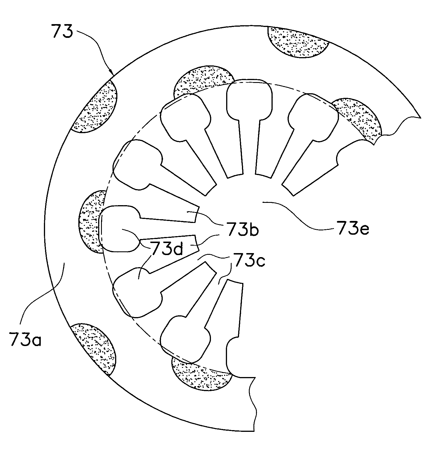
[0044] FIG. 9 will be used below to explain the change in the load-displacement characteristics when compression residual stress is applied to a portion of the resilient portion 73a of the diaphragm spring 73.

[0045] First, when compression residual stress is applied in a conventional manner to the entire surface of a concave surface 80 on the resilient portion 73a, the size of the load will be different than when shot-peening is not performed. However, the qualitative trend of the load-displacement will the same, and a widening of the flat portion near the high load peak shown in FIG. 9 will not be seen. Thus conventionally, an increase in the durability of the resilient portion 73a is possible even if compression residual stress is applied by shot-peening, but changing the load-displacement characteristics thereof was though to be difficult.

[0046] However, as noted above, it is now understood that when shot-peening is performed on only...


PUM

PropertyMeasurementUnit
resilientaaaaaaaaaa
compression residual stressaaaaaaaaaa
surface areaaaaaaaaaaa

Abstract

A method of producing a plate spring is disclosed which allows one to adjust the load-displacement characteristics thereof to a desired degree. The method includes stamping slits and a small diameter hole from a disk-shaped plate member, and forming the plate spring into a cone shape. Shot-peening is then performed on a resilient portion of the plate spring that retains a flat cone shape in the free state. Furthermore, shot-peening is performed on only a portion of the resilient portion and not on the entire surface of the plate spring.

Description

[0001] 1. Field of the Invention[0002] The present invention relates to a method for producing a plate spring.[0003] 2. Background Information[0004] Plate springs are conventionally employed in automobile components. An example of this type of plate spring is a diaphragm spring employed in a clutch cover assembly of a clutch device for use in an automobile. The diaphragm spring is a disk-shaped member that is used in the clutch cover assembly, and is comprised of an annular resilient portion and a plurality of levers that extend inward in the radial direction from the resilient portion. Either the inner or outer periphery of the annular resilient portion is supported by the clutch cover, and the periphery not supported thereby biases a pressure plate. A release mechanism that includes a bearing and the like engages with the tips of the plurality of the levers.[0005] With this type of diaphragm spring, plastic working such as shot-peening is typically performed on either both sides o...

Claims


Application Information

Patent Timeline
Patent Type & Authority Applications(United States)
IPC IPC(8): B23P15/00B24C1/10C21D7/06F16D13/58F16F1/02F16F1/32
CPCB23P15/00C21D7/06F16F2226/00F16D13/583F16F1/32C21D2221/00
Inventor DOUMAN, YASUNORIKIMURA, HIROSHIFUJII, TORU
Owner EXEDY CORP
Why Eureka
Try Eureka