

Lamp unit and infrared night-vision system
a technology of infrared night vision and lamp unit, which is applied in the direction of gas-filled discharge tubes, electric discharge lamps, solid cathodes, etc., can solve the problems of halogen bulb life and performance change, and the durability and life of halogen bulbs will be reduced
- Summary
- Abstract
- Description
- Claims
- Application Information
AI Technical Summary
Benefits of technology
Problems solved by technology
Method used
Image

Examples
first embodiment
[0039] The lamp unit 10 of the first embodiment is further explained in this first example. In the first example, the cesium halide and the mercury are enclosed in the hollow 22 of the discharge tube 20 of the above-mentioned lamp unit 10. Here, CsI is enclosed as a cesium halide. The discharge tubes having 8.times.6=48 types of combinations of the quantity M1 of CsI and the quantity M2 of mercury were manufactured. The quantity M1 of CsI was varied from 0.05 mg to 0.40 mg, and the quantity M2 of mercury was varied from 0.4 mg to 1.4 mg.
[0040] FIG. 3 shows the measured result of the tube voltages VL of emission in these discharge tubes. The standard required as a headlight of vehicles is taking into consideration, and the black triangle mark was given to the discharge tube that does not satisfy the criterion of VL=85.+-.17 (V) as shown in FIG. 3. As shown in FIG. 3, in order to meet this criterion, it is desirable to design the discharge tube so that the quantity M1 of CsI and the q...
second example
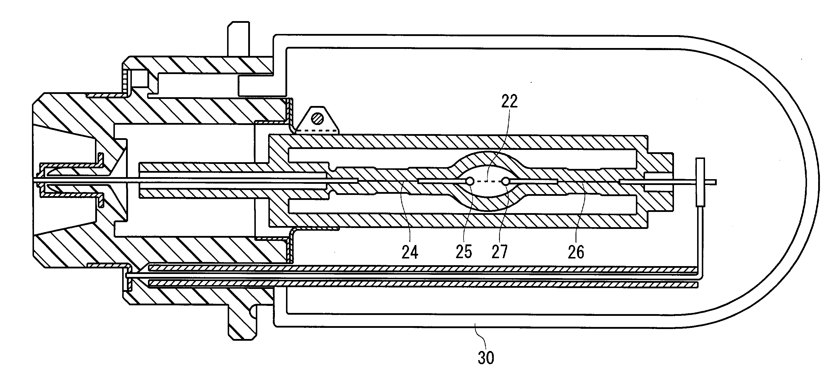
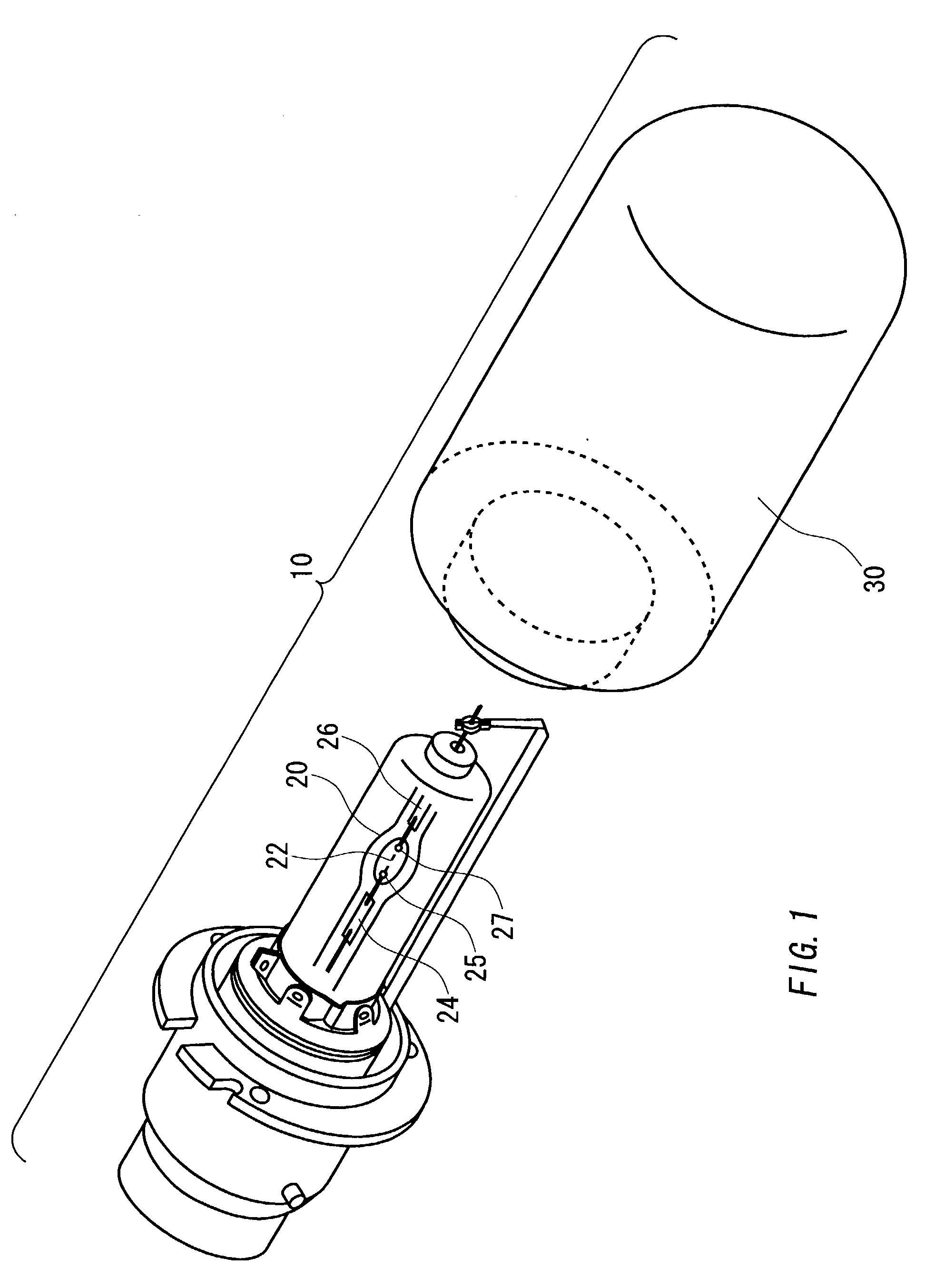
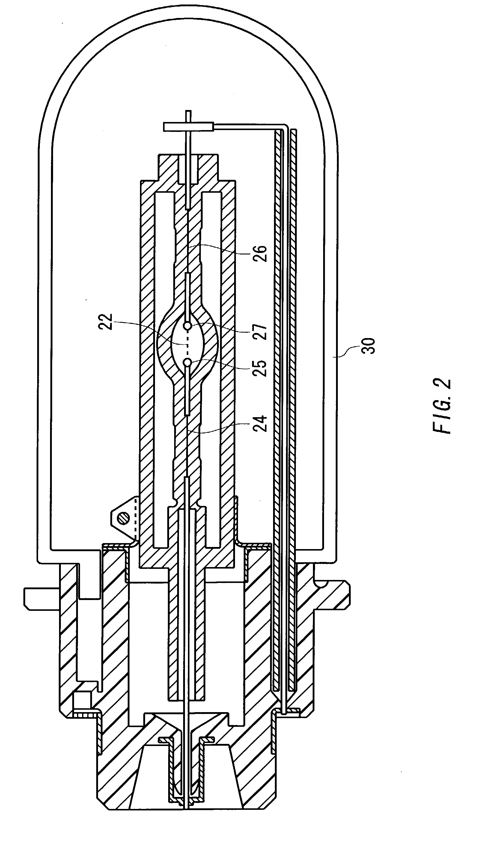
[0049] The lamp unit 10 of the above-mentioned embodiment is further explained using a second example. As an example of the lamp unit 10, the discharge tubes 20 shown in FIGS. 1 and 2 were used. 0.15 mg of cesium iodide, 0.9 mg of mercury, 0.3 mg of iodide sodium iodide and scandium iodide, the proportion of which is 65 to 35, were enclosed in the hollow 22 of a discharge tube 20.
[0050] FIG. 4 shows a measured spectrum distribution of one unit of discharge tube 20 of the second example in the visible light region depending on the light wavelength when the electric power of a discharge tube 20 is 35 W. In FIG. 4, a spectrum distribution of the discharge tube 20 of the second example in the wavelength range from 400 nm to 800 nm is shown.
[0051] FIG. 5 shows a spectrum distribution of the lamp unit 10, which has the discharge tube 20 and the infrared filter 30. In FIG. 5, a spectrum distribution of the near-infrared light of the discharge tube 20 of the second example in the wavelength...
third example
[0057] The lamp unit 10 is further explained in a third example. Cesium halide, mercury, sodium halide, and rare earth halide are enclosed in the hollow 22 of the discharge tube 20 of the lamp unit 10 of the third example. Here, CsI is enclosed in the hollow 22 of the discharge tube 20 as cesium halide. Moreover, NaI is enclosed in the hollow 22 of the discharge tube 20 as a sodium halide, and ScI.sub.3 is enclosed in the hollow 22 of the discharge tube 20 as a rare earth halide with the NaI.
[0058] The discharge tubes having 8.times.7=56 types of combinations of the quantity M1 of CsI and the total quantity M4 of NaI and ScI were manufactured. The quantity M1 of CsI was varied from 0.05 mg to 0.40 mg, and the total quantity M4 of NaI and ScI was varied from 0.03 mg to 0.3 mg.
[0059] FIG. 8 shows all luminous flux of the light emitted from the discharge tubes.
[0060] The standard of luminous flux required as a halogen lamp is taking into consideration as a reference, and the black tria...
PUM
 Abstract
Description
Claims
Application Information