Methods and apparatus for cardiac valve repair

a technology for cardiac valves and apparatuses, applied in the field of medical methods, devices and systems, can solve the problems of affecting the repair effect of cardiac valves,

Active Publication Date: 2004-02-12
EVALVE
View PDF99 Cites 586 Cited by
  • Summary
  • Abstract
  • Description
  • Claims
  • Application Information

AI Technical Summary

Benefits of technology

[0019] The methods of the present invention will usually comprise accessing a patient's vasculature at a location remote from the heart, advancing an interventional tool through the vasculature to a ventricle and / or atrium, and engaging the tool against a tissue structure which forms or supports the atrioventricular valve. By engaging the tool against the tissue structure, the tissue structure is modified in a manner that reduces valve leakage or regurgitation during ventricular systole. The tissue structure may be any of one or more of the group consisting of the valve leaflets, chordae, the valve annulus, and the papillary muscles. Optionally, the interventional tool will be oriented relative to the atrioventricular valve and / or tissue structure prior to engaging the tool against the tissue structure. The interventional tool may be self-orienting (e.g., pre-shaped) or may include active mechanisms to steer, adjust, or otherwise position the tool. Alternatively, orientation of the interventional tool may be accomplished in whole or in part using a separate guide catheter, where the guide catheter may be pre-shaped and / or include active steering or other positioning means. In all cases, it will usually be desirable to confirm the position prior to engaging the valve leaflets or other tissue structures. Such orienting step may comprise positioning the tool relative to a line of coaptation in the atrioventricular valve, e.g., engaging positioning elements in the valve commissures.
[0020] In a first aspect of the method of the present invention, the tissue structure comprises the valve leaflets and the engaging step comprises attaching one or more opposed points on or along the valve leaflets together. In the case of the bicuspid mitral valve, the attachment points may be located at or near the center of each leaflet, creating a generally symmetric structure with two openings, i.e., between the attachment point(s) and each of the two commissures. Alternatively, the attachment points may be close to each of the commissures. Both will effectively reduce the area in which the valve can open. In the case of the tricuspid valve, any two of the three leaflets can be partially or totally closed together or all three may be partially closed together.
[0021] In both cases, the attachment of the valve leaflets may be performed in a variety of ways, including suturing, clipping, stapling, riveting, gluing, fusing, or the like. While each of these approaches may differ significantly in the protocols and devices used for performing them, the end result will be the same, i.e., improved ability of the atrioventricular valve to close against the elevated pressures within the ventricle during systole. In order to improve apposition of the valve leaflets, it may be preferred to attach the leaflets at a point spaced inwardly from the free edge of the leaflet. Usually, the attachment point within the valve leaflet will be located from 1 mm to 4 mm inward from the free edge.

Problems solved by technology

While such an approach may be effective for some purposes, the difficulty in capturing the valve leaflets initially may still be present.
Mitral valve access is generally more difficult than tricuspid valve access.

Method used


Image

  • Methods and apparatus for cardiac valve repair
  • Methods and apparatus for cardiac valve repair
  • Methods and apparatus for cardiac valve repair

Examples


Embodiment Construction

I. Cardiac Physiology

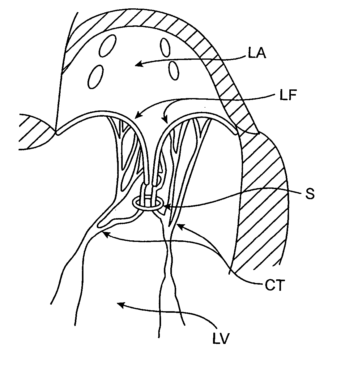
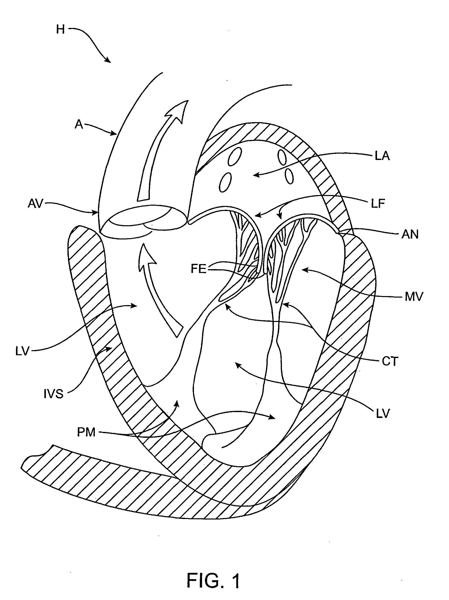
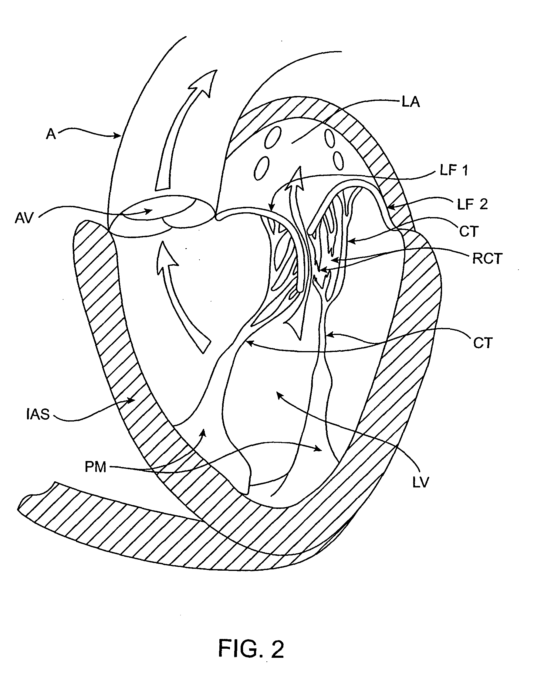
[0109] The left ventricle LV of a normal heart H in systole is illustrated in FIG. 1. The left ventricle LV is contracting and blood flows outwardly through the tricuspid (aortic) valve AV in the direction of the arrows. Back flow of blood or "regurgitation" through the mitral valve MV is prevented since the mitral valve is configured as a "check valve" which prevents back flow when pressure in the left ventricle is higher than that in the left atrium LA. The mitral valve MV comprises a pair of leaflets having free edges FE which meet evenly to close, as illustrated in FIG. 1. The opposite ends of the leaflets LF are attached to the surrounding heart structure along an annular region referred to as the annulus AN. The free edges FE of the leaflets LF are secured to the lower portions of the left ventricle LV through chordae tendineae CT (referred to hereinafter as the chordae) which include plurality of branching tendons secured over the lower surfaces of each o...


PUM


Abstract

The methods, devices, and systems are provided for performing endovascular repair of atrioventricular and other cardiac valves in the heart. Regurgitation of an atrioventricular valve, particularly a mitral valve, can be repaired by modifying a tissue structure selected from the valve leaflets, the valve annulus, the valve chordae, and the papillary muscles. These structures may be modified by suturing, stapling, snaring, or shortening, using interventional tools which are introduced to a heart chamber. Preferably, the tissue structures will be temporarily modified prior to permanent modification. For example, opposed valve leaflets may be temporarily grasped and held into position prior to permanent attachment.

Description

CROSS-REFERENCES TO RELATED APPLICATIONS[0001] This application is a continuation of U.S. application Ser. No. 09 / 544,930 (Attorney Docket No. 020489-000110US), filed Apr. 7, 2000, which claimed the benefit under 35 USC 119(e) of U.S. Provisional Application No. 60 / 128,690 (Attorney Docket No. 020489-000100US), filed on Apr. 9, 1999 under 37 CFR .sctn.1.78(a). The full disclosures of which are incorporated herein by reference.[0002] 1. Field of the Invention[0003] The present invention relates generally to medical methods, devices, and systems. In particular, the present invention relates to methods, devices, and systems for the endovascular or minimally invasive surgical repair of the atrioventricular valves of the heart, particularly the mitral valve.[0004] Mitral valve regurgitation is characterized by retrograde flow from the left ventricle of a heart through an incompetent mitral valve into the left atrium. During a normal cycle of heart contraction (systole), the mitral valve ...

Claims


Application Information

Patent Timeline
Patent Type & Authority Applications(United States)
IPC IPC(8): A61B17/00A61B17/04A61B17/06A61B17/064A61B17/068A61B17/12A61B17/122A61B17/128A61F2/24
CPCA61B8/10A61F2/2457A61B17/04A61B17/0401A61B17/0469A61B17/0482A61B17/0487A61B17/0625A61B17/064A61B17/0643A61B17/0644A61B17/068A61B17/07207A61B17/08A61B17/122A61B17/1227A61B17/1285A61B17/29A61B18/1492A61B18/18A61B18/20A61B2017/00243A61B2017/00575A61B2017/00579A61B2017/00588A61B2017/00592A61B2017/00606A61B2017/00623A61B2017/00783A61B2017/00867A61B2017/0404A61B2017/0409A61B2017/0417A61B2017/0419A61B2017/0443A61B2017/045A61B2017/0464A61B2017/047A61B2017/0472A61B2017/0474A61B2017/0488A61B2017/0496A61B2017/06052A61B2017/06057A61B2017/06076A61B2017/061A61B2017/06171A61B2017/0641A61B2017/0649A61B2017/088A61B2017/2926A61B2018/00291A61F2/2445A61B17/00234A61F2/246A61B2017/2931A61B2017/2906
Inventor ST. GOAR, FREDERICK G.FANN, JAMES I-LINDEEM, MARK E.GIFFORD, HANSON S. IIIDIECK, MARTIN SMARTIN, BRIAN B.FAN, SYLVIA WEN-CHINGOLDFARB, ERIK A.DELL, KENT D.POWELL, FEROLYN T.
Owner EVALVE
Why Eureka
Try Eureka