Microphysiometer

a microphysiometer and micro-calorimeter technology, applied in the field of microphysiometers, can solve the problems of common rejection mode, non-compatibility of micro-calorimeter batch systems with high-throughput requirements, and problems concerning baseline stability, so as to facilitate the integration of sensors and fluidics on the same chi

Inactive Publication Date: 2004-02-26
TTP LABTECH
View PDF6 Cites 32 Cited by
  • Summary
  • Abstract
  • Description
  • Claims
  • Application Information

AI Technical Summary

Benefits of technology

0066] The main advantages of a thermopile are:
0067] The thermopile is a self-generating offset-less device, as the heat flowing through it supplies the power for the output signal. As a result there is no offset drift and no interference caused by power supplies.
0068] The sensitivity of the thermopile is hardly influenced by variations in the electrical parameters across the wafer or by the temperature.
0069] The thermopile can be optimised in terms of dimension and number of thermo-electric strips. The optimum is found analytically, with the help of MATLAB. The other sensing principles and supporting structures (e.g. the resistors in the capillary walls) are designed to fit in this optimised thermopile chip architecture
0071] The substrate as ...

Problems solved by technology

These micro-calorimeter batch systems are non-compatible with high-throughput requirements due to the relatively large volumes, the apparatus' closed structure and long cycle times (typical cycle times are 2 to 3 hours).
A main disadvantage of these devices is that they are configured in such a way that the reference temperature is the temperature of the silicon border.
This leads to problems concerning baseline stability and common rejection mode since no differential measurements are used.
Additionally, these devices are not compatible with standard robotics used in high throughout screening since no receiving zones are in...

Method used


Image

  • Microphysiometer
  • Microphysiometer
  • Microphysiometer

Examples


example 1

Development of a Microphysiometer Comprising a Thermopile as Differential Detection Means

[0102] A microphysiometer was developed, which comprises a device which allows the detection of extremely small temperature differences between two reaction vials, which is biocompatible and of which an array can be formatted which has the footprint of a microtitreplate. In order to correspond to a 96-well plate format, the distance between the centre of the two substantially identical receiving zones of the device was designed to be 9 mm.

[0103] As substrate material for the device silicon was selected.

[0104] The herein described device was developed for processing on an 8 mm membranous chip. However, it will be understood that, the use of other substrate material may dictate adjustments in certain described settings.

[0105] The use of silicon as substrate material provides the possibility of integrating the sensors and fluidics on the same chip, so that sample volumes can be minimalized (minimal...

example 2

Development of Different Arrays of the Devices

[0119] The device as developed in Example 1 was designed for a sensor-arrayed chip with the footprint of a standard 96-well titre plate, to be compatible with pharmaceutical robotics for dispensing and titre plate handling (the 96-well format of microtitre plates being considered as the reference for the moment). The distance between adjacent wells in this format is 9 mm. For formats derived from this reference, the inter-well distance is 9 mm divided by the miniaturisation factor. The miniaturisation factor is defined as: 3 m = n_wells 96

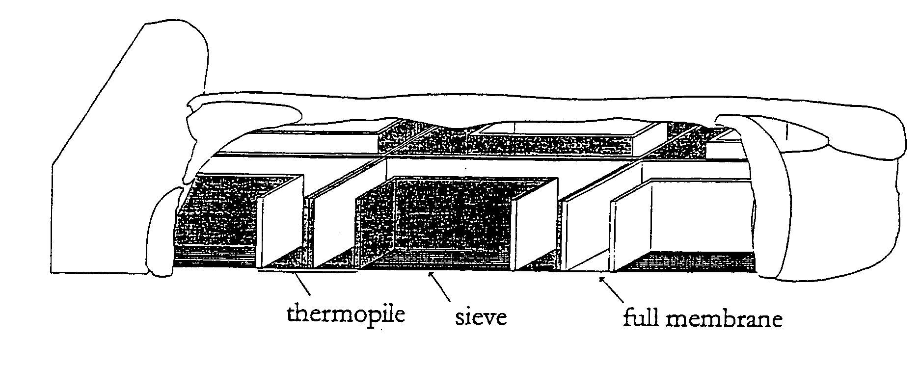
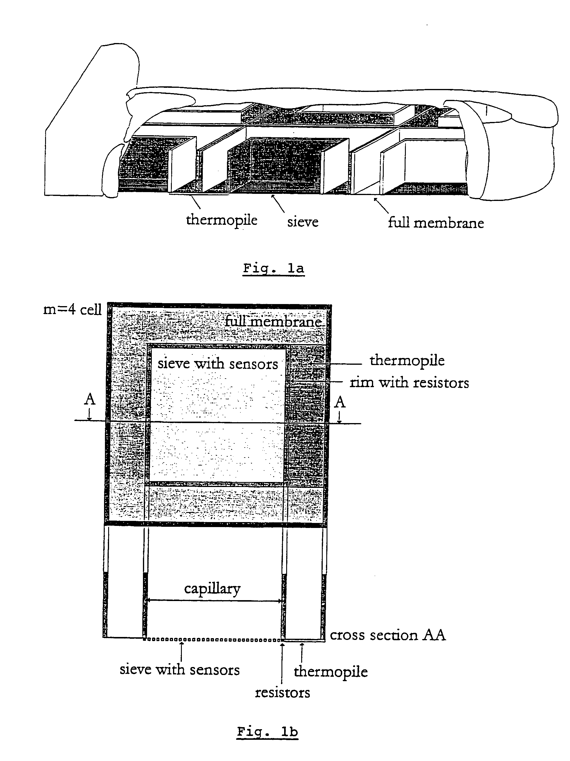
[0120] with n_wells the number of wells. The format used in the present example is a 1536-well (m=4), with 8*(8*12) devices on the substrate.

[0121] A 3-D view of a part of the array is shown in FIG. 1a. A thermopile connects each two neighbouring cells.

example 3

Applications of the Microphysiometer of the Present Invention

[0122] The device of the present invention makes it possible to measure the interaction between two molecules in a very sensitive, physiologically relevant way, while its scale allows integration into industrial robotics, opening enormous possibilities for its use as a high-throughput screening tool.

[0123] A. Industrial Enzyme Discovery

[0124] According to a preferred embodiment of the invention the device is used for screening enzyme activity in the identification of new enzymes.

[0125] The field of industrial enzyme discovery is now profiting from the genomics and assay technology revolution. Analysis of gene expression libraries from various organisms allows the discovery of many enzymes, or biocatalysts, which brings new solutions to industry. The use of enzymes to effect chemical transformations, also called biocatalysis, has grown enormously over the last 15 years, and is now a major contributor to industrial synthesis...


PUM

PropertyMeasurementUnit
Lengthaaaaaaaaaa
Lengthaaaaaaaaaa
Lengthaaaaaaaaaa

Abstract

The present invention is related to an array device for monitoring the effect of a physical or chemical stimulus on multiple small samples, said array device comprising a supporting substrate at least two array elements that are separated from each other by a isolation zone, said array elements comprising:.A receiving zone arranged to provide a contact between said one of said samples and said physical or chemical stimulus, said receiving zone having a cross-section smaller than 10 mm..A heat detection means arranged to perform a measurement of heat between said receiving zone and a reference, and said isolation zone being formed by at least part of said supporting substrate characterised in that said supporting substrate has sufficient strength to support said array device and said isolation zone is arranged to thermally isolate said array elements.

Description

[0001] The present invention is related to a device and method for calorimetric measurements, especially to a high throughput screening device for detecting energy changes.STATE OF THE ART[0002] Calorimetry in general is a measurement principle that detects all processes that occur in a reaction vessel. Calorimetry has several advantages: calorimetry is the most general detection principle, since most processes, physical, chemical or biological are accompanied by changes in heat content. This can be useful in the analysis of very complex processes, because is more likely that unknown phenomena will be discovered. Moreover, the change of temperature of a reaction volume is dependent upon the concentration of the reagents, not upon the absolute quantity, offering the possibility of miniaturisation. Additionally, calorimetric methods are not dependent upon the sample form (the sample can be solid, liquid, gaseous, or any combination thereof, and neither colour, optical transparency, no...

Claims


Application Information

Patent Timeline
IPC IPC(8): C12M1/34C12N15/09G01N25/20C12N15/10G01K7/02G01N25/48G01N33/15G01N33/50G01N33/53G01N37/00
CPCC12N15/1086G01N33/5302G01N25/4866G01K7/028
Inventor VERHAEGEN, KATARINA
Owner TTP LABTECH
Why Eureka
Try Eureka