
Method and device for heat treatment

Inactive Publication Date: 2004-03-11
TOKYO ELECTRON LTD
View PDF4 Cites 4 Cited by
  • Summary
  • Abstract
  • Description
  • Claims
  • Application Information

AI Technical Summary

Benefits of technology

[0006] A more specific object of the present invention is to provide a heat treatment apparatus and method which can achieve a high throughput when applying a heat treatment to a glass substrate.
[0010] Further, the heat treatment method according to the above-mentioned present invention may includes a step of dividing the glass substrate placed in said reaction container into a plurality of areas and supplying independently a gas for heat exchange to each of the areas; a step of detecting a temperature of each of the divided areas of said glass substrate; and a step of controlling at least one of an amount of flow and a temperature of the gas for heat exchange to be supplied to each divided area. Thereby, heating and cooling of the glass substrate can be performed with a further higher in-plane uniformity.

Problems solved by technology

The hot-wall type heat treatment apparatus requires a long time for heating and cooling a substrate.
However, since the electrostatic chuck cannot be used in the hot-wall type, a large gap is present between a substrate and a placement stage.
For this reason, if an attempt is made to take measures of a cold-wall type, especially in a case of a large-size LCD substrate, it is difficult to cool down uniformly and rapidly.
Therefore, when an attempt is made to incorporate a hot-wall type heat treatment apparatus which performs a heat treatment of an LCD substrate, it takes a long time to heat and cool the substrate by the heat treatment apparatus, and, thus, there is a problem in that a function of a high throughput which is provided by a cluster tool cannot be sufficiently used.

Method used


Image

  • Method and device for heat treatment
  • Method and device for heat treatment
  • Method and device for heat treatment

Examples


first embodiment

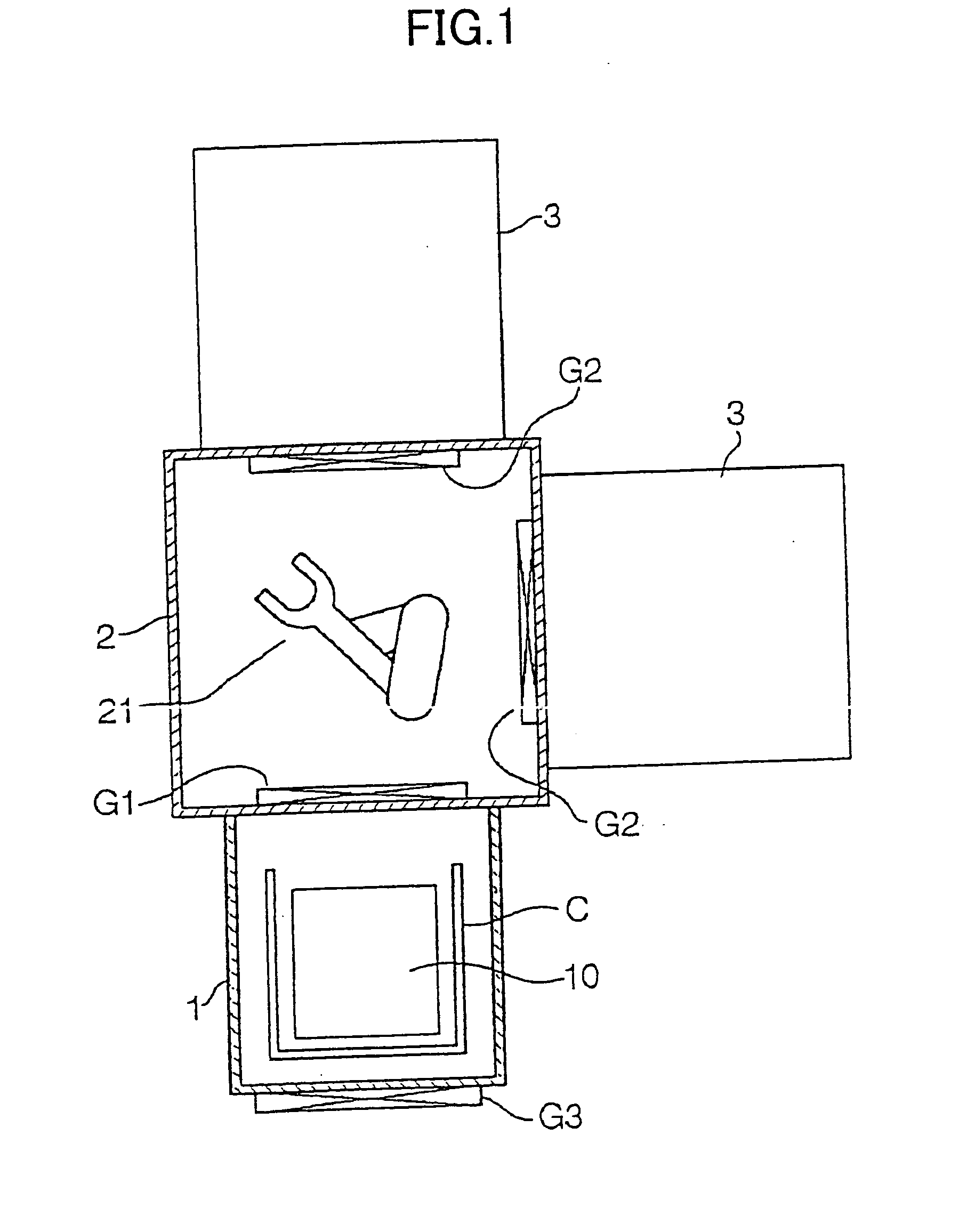
[0020] FIG. 1 is a plan view showing an outline structure of a heat treatment apparatus according to the present invention. The heat treatment apparatus shown in FIG. 1 comprises a carrier chamber 1, a conveyance chamber 2, and a plurality of hot-wall type heat treatment units 3 (two units in the figure). The carrier chamber 1 and the conveyance chamber 2 are airtightly connected through a gate valve G1. Additionally, the conveyance chamber 1 and the heat treatment units 3 are connected through a gate valve G2, respectively.

[0021] The carrier chamber 1 is an airtight chamber for carrying in and out a carrier C, which is a convey tool for conveying a plurality of rectangular LCD substrates by retaining in a shelf-like state, between outside of the apparatus through a gate door G3. The conveyance chamber 2 provides a convey means 21 which comprises a multi-joint arm. The convey means 21 is constituted so that the LCD substrates 10 can be delivered between the carrier C in the carrier ...

third embodiment

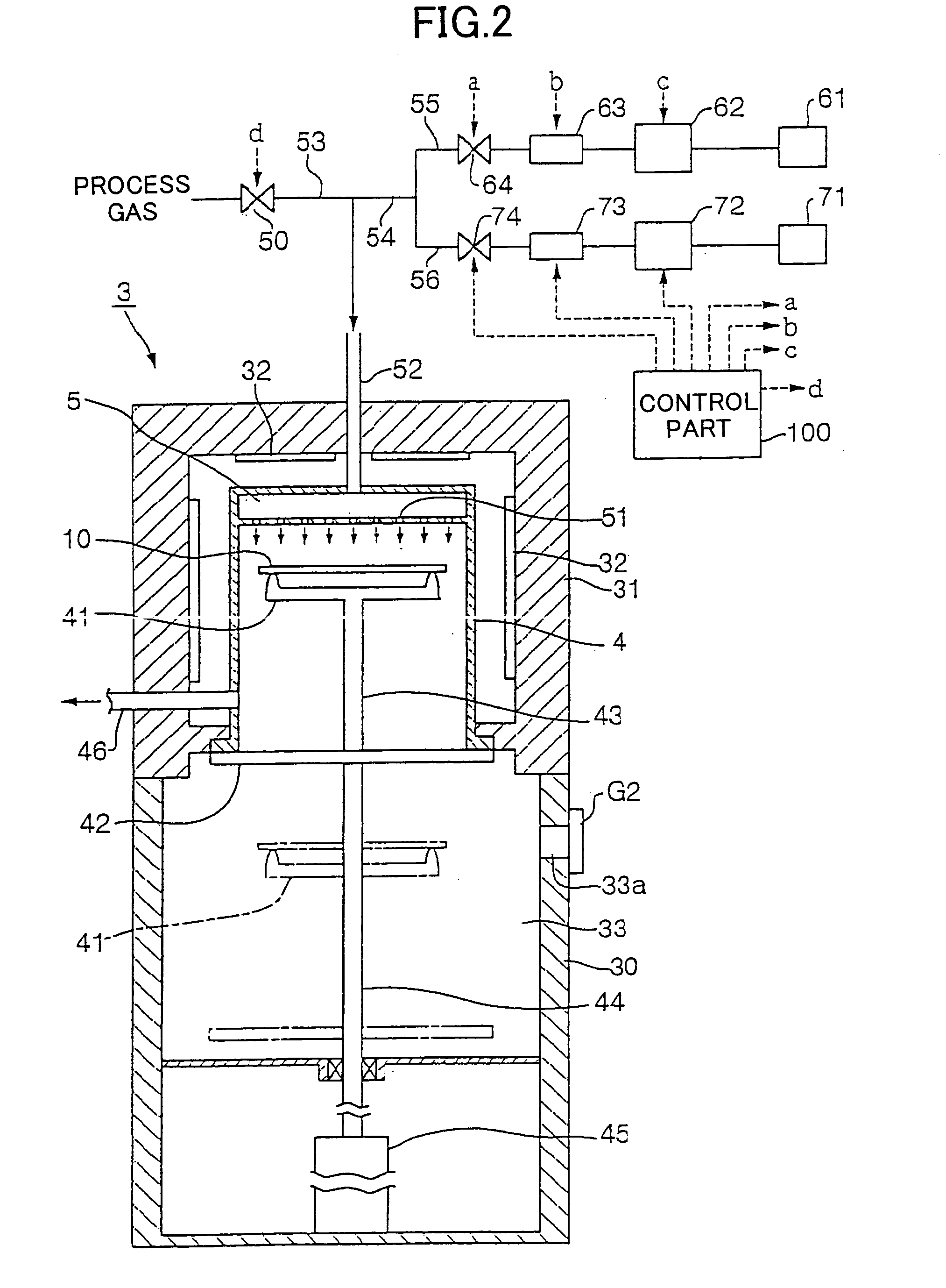
[0042] FIG. 6 is a diagram showing the present invention. In this embodiment, an amount of heat exchange gas sufficient for one time heat exchange is accumulated in each of the gas-supply pipe 55 for the first heat exchange gas and the gas-supply pipe 56 for the second heat exchange gas. Moreover, for example, tanks 60 and 70 equipped with a temperature control part and valves 65, 66, 75 and 76 are provided. The capacity and internal pressure of the tanks 60 and 70 and the supply flows of the first and second heat exchange gas is set in accordance with a balance between an evacuation capacity of an exhaust pump which is connected to the exhaust pipe 46 and not illustrated, and a pressure inside the reaction container 4 at the time of start of heat exchange (start of heating or cooling).

[0043] In this example, when supplying the first heat exchange gas (second heat exchange gas) to the reaction container 4, after opening the valves 64 and 66 (74, 76) and completing a heat exchange, a...


PUM

PropertyMeasurementUnit
Temperatureaaaaaaaaaa

Abstract

After carrying an LCD substrate in a reaction container of a heat treatment unit, blowing a previously heated helium gas from a gas supply part, which opposes to the surface of the LCD substrate, over the entire surface of the LCD substrate. The temperature of the LCD substrate is raised by radiation heat of a heater and heat exchange with the helium gas. After performing CVD or annealing in the reaction container, cooling the LCD substrate by blowing a gas for heat exchange having a temperature about a room temperature from the gas supply part over the entire surface of the LCD substrate. Return the cooled LCD substrate to a carrier in the carrier chamber via a conveyance chamber.

Description

[0001] The present invention relates to heat treatment method and heat treatment apparatus and, more particularly, to a heat treatment method and a heat treatment apparatus which are used for manufacturing semiconductors.[0002] A liquid crystal panel is used as a display of computers or televisions. A glass substrate for liquid crystal displays (hereinafter, referred to as an LCD substrate) has been enlarged increasingly in recent years. Various semiconductor manufacturing processes are performed for forming devices such as a thin film transistor (TFT) on the LCD substrate. Among such processes, a heat treatment process is performed by a single-wafer type cold-wall heat treatment apparatus, which processes substrates one by one. This apparatus heats a substrate carried in a chamber from above by a heating lamp. As for a large-size LCD substrate, since heat radiation from a circumferential edge is large, it is preferable to use a hot-wall type heat treatment apparatus which heats a s...

Claims


Application Information

Patent Timeline
IPC IPC(8): C03B32/00C23C16/44C23C16/455C23C16/46C23C16/56G02F1/13F27D7/02F27D9/00H01L21/00H01L21/22H01L21/31H01L21/324H01L21/677
CPCC23C16/4557C23C16/46H01L21/67739H01L21/324H01L21/67109C23C16/56
Inventor MATSUOKA, TAKAAKI
Owner TOKYO ELECTRON LTD
Features
  • Generate Ideas
  • Intellectual Property
  • Life Sciences
  • Materials
  • Tech Scout
  • Unparalleled Data Quality
  • Higher Quality Content
  • 60% Fewer Hallucinations
Learn More