Process for regenerating a nitrogen oxides storage catalyst

a nitrogen oxide and storage catalyst technology, applied in the direction of electrical control, separation process, other chemical processes, etc., can solve the problems of difficult regenerating of nitrogen oxide storage components, difficult to convert nitrogen oxides to harmless nitrogen gas, and difficult to achieve the effect of regenerating nitrogen oxide storage components

Inactive Publication Date: 2004-03-25
OMG AG & CO KG
View PDF3 Cites 45 Cited by
  • Summary
  • Abstract
  • Description
  • Claims
  • Application Information

AI Technical Summary

Problems solved by technology

Unfortunately, due to the high oxygen content of diesel exhaust gas, it is difficult to convert the nitrogen oxides to harmless nitrogen gas.
Nitrogen oxide storage catalyst regeneration functions well above a threshold temperature between approximately 170.degree. C. and 250.degree. C., but regeneration is difficult below this temperature range.
This causes problems with regenerating nitrogen oxide storage components, especially after prolonged storage periods.
However, at low temperatures a dsubstantial amount of the nitrogen oxide being released leaves the converter unreduced, probably due to slow kinetics of the chemical reactions involved in nitrogen oxide conversion.
Furthermore, the storage components are only partly cleared, and some nitrates remain in the storage material, lowering the storage capacity for the next storage cycle.
Heating measures in lean conditions by post injection are ineffective at improving the performance of nitrogen oxide storage catalysts, since the temperature increase achieved drops very quickly after switching back to normal operation mode.
At temperatures below the threshold value, conventional regeneration strategies are unable to fully restore the original storage capacity of the catalyst.
This leads to strong emissions of carbon monoxide and hydrocarbons during the regeneration period.
When a nitrogen oxide storage catalyst is operated over a prolonged period at low exhaust gas temperatures, regeneration gets worse, and after each regeneration the residual nitrogen oxides remaining on the catalyst increases.
This procedure yields poor results at gas temperatures below a certain threshold.

Method used


Image

  • Process for regenerating a nitrogen oxides storage catalyst
  • Process for regenerating a nitrogen oxides storage catalyst
  • Process for regenerating a nitrogen oxides storage catalyst

Examples


example 1

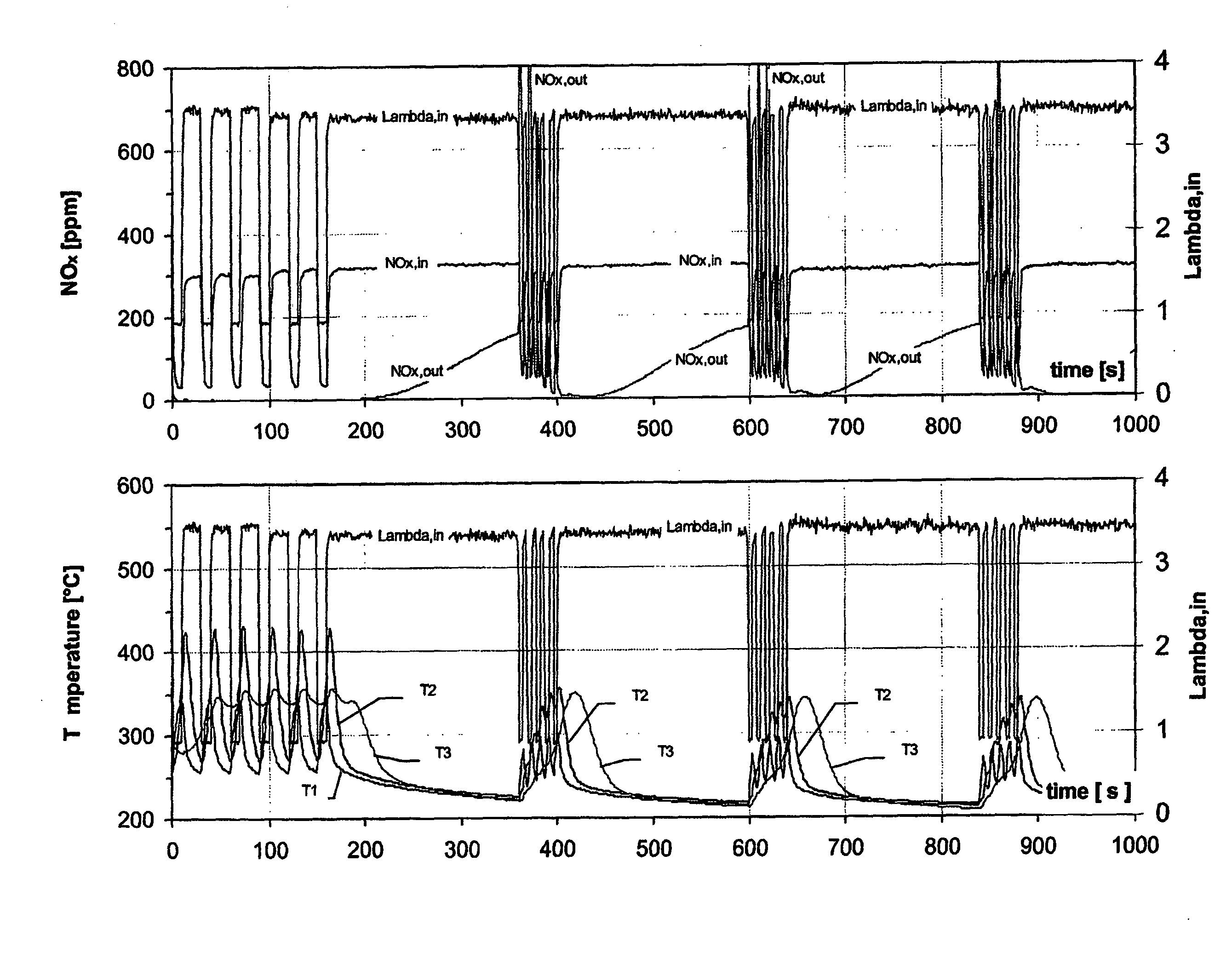
[0032] The novel pulsed regeneration strategy of the invention was applied during the operation of a nitrogen oxide storage catalyst arranged in the exhaust system of a diesel engine. The diesel engine was a common rail engine with a power rating of 90 kW and a displacement volume of 2.2 liters. The nitrogen oxide storage catalyst consisted of a honeycomb carrier with a diameter 14.38 cm (5.66 inches), length 15.24 cm (6 inches) and volume 2.47 liters. The cell density of the carrier was 62 cm.sup.-2 (400 inches.sup.-2).

[0033] The storage catalyst had been applied to this catalyst carrier with a concentration of 280 g / liter of honeycomb carrier. The storage component was barium oxide. The storage catalyst further contained platinum and rhodium in a weight ratio of 10:1 and a combined concentration of 3.88 g / liter (110 g / ft.sup.3).

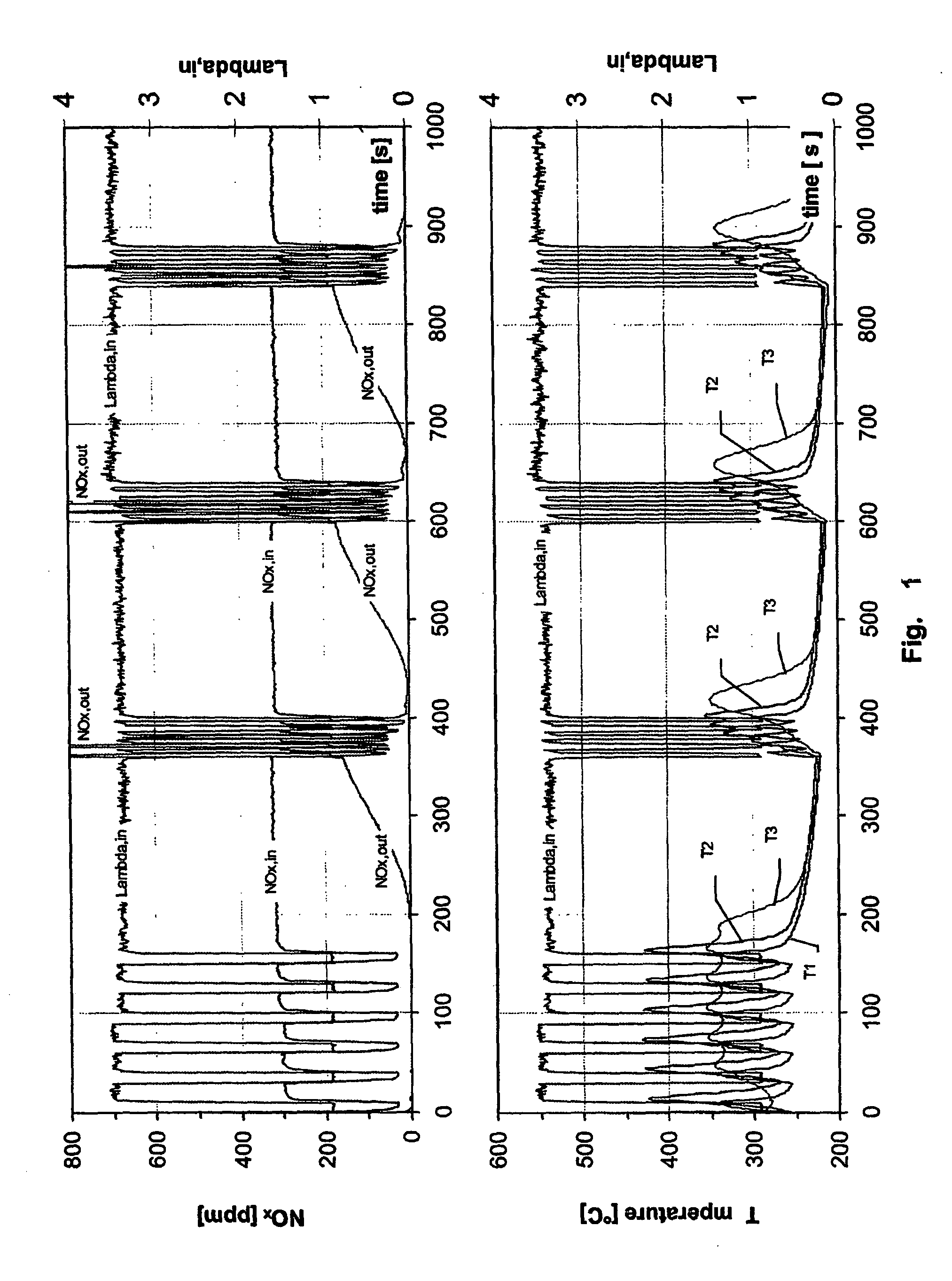
[0034] FIG. 1 shows measurement scans of various quantities of the exhaust gas and of the catalyst over a 1000 second operation period of the diesel engine...


PUM

PropertyMeasurementUnit
threshold temperatureaaaaaaaaaa
timeaaaaaaaaaa

Abstract

The present invention provides a process and a device for regeneration of a nitrogen oxide storage catalyst in the exhaust system of a diesel engine. The process comprises a first and a second regeneration strategy. The first regeneration strategy is applied when the exhaust gas temperature is above a threshold value and comprises changing the air/fuel-ratio from a lean to a rich value during a first regeneration period. The second regeneration strategy is applied when the exhaust gas temperature is below a threshold value and comprises switching the air/fuel-ratio back and forth between lean and rich air/fuel-ratios, forming a sequence of between 2 and 10 rich pulses and between 2 and 10 lean pulses during a second regeneration period.

Description

[0001] The present invention relates to cleaning exhaust gas of a diesel engine. More precisely, it is directed to lowering the content of nitrogen oxide contained in the exhaust gas by using a nitrogen oxide storage catalyst.BACKGROUND OF INVENTION[0002] Diesel engines belong to the category of lean-bum engines and are operated with lean air / fuel-ratios. The air / fuel-ratio is calculated from the mass of air supplied to the engine in relation to the mass of fuel. In normal fuels for internal combustion engines such as diesel engines or gasoline engines, 14.6 kilograms of air are needed for the complete combustion of 1 kilogram of fuel, which is an air / fuel-ratio of approximately 14.6. Air / fuel-ratios above that value are lean, and air / fuel-ratios below that value are rich. The exhaust gas leaving the engine exhibits the same air / fuel-ratio as the air / fuel-mixture supplied to the engine, provided that no adsorption or desorption processes occur within the engine.[0003] Frequently the...

Claims


Application Information

Patent Timeline
Patent Type & Authority Applications(United States)
IPC IPC(8): F02D45/00B01D53/94B01D53/96B01J38/00F01N3/08F01N3/20F01N3/24F01N3/28F02D41/02F02D41/04
CPCB01D53/9495B01D53/96F01N3/0885Y02T10/20F01N2560/026F02D41/0275F01N2430/06Y02T10/12B01D53/94B01J38/00F01N3/18
Inventor ROHR, FRIEDEMANNKATTWINKEL, PETERPETER, STEFAN D.KREUZER, THOMASLOX, EGBERT
Owner OMG AG & CO KG
Why Eureka
Try Eureka