

Steam engine
a steam engine and steam technology, applied in the direction of engines, machines/engines, mechanical devices, etc., can solve the problems of difficult to increase the mechanical energy taken out of the thermal energy, and the inability to perfectly prevent the emergence of water droplets in the steam turbin
- Summary
- Abstract
- Description
- Claims
- Application Information
AI Technical Summary
Benefits of technology
Problems solved by technology
Method used
Image

Examples
first embodiment
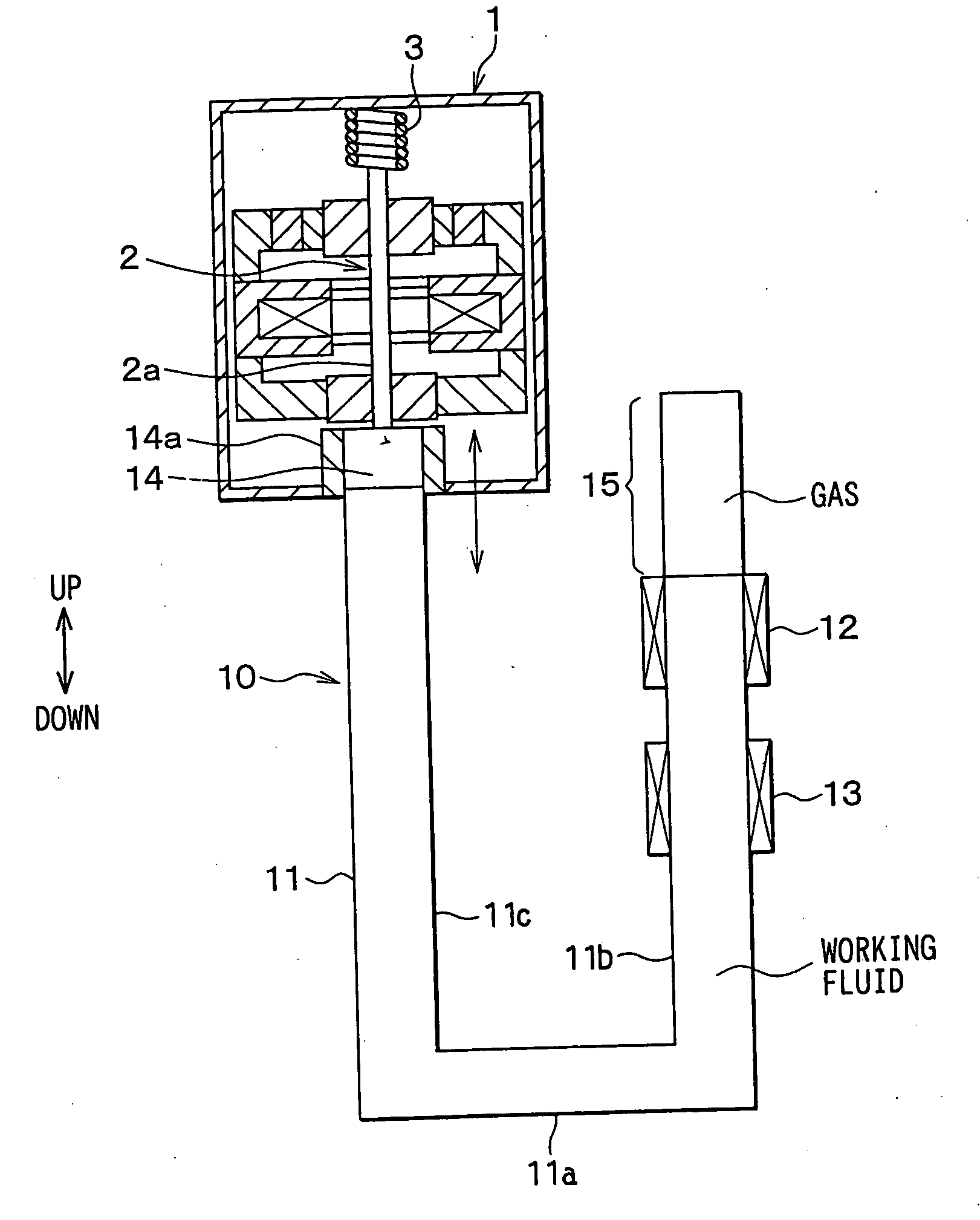
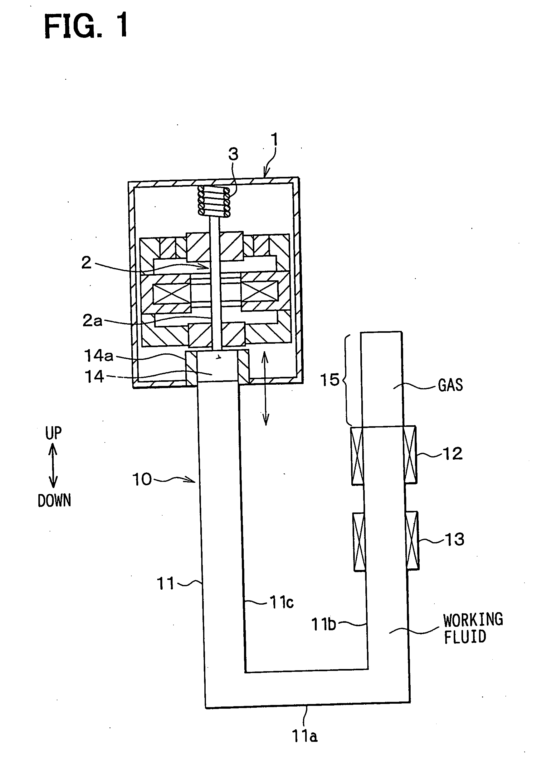
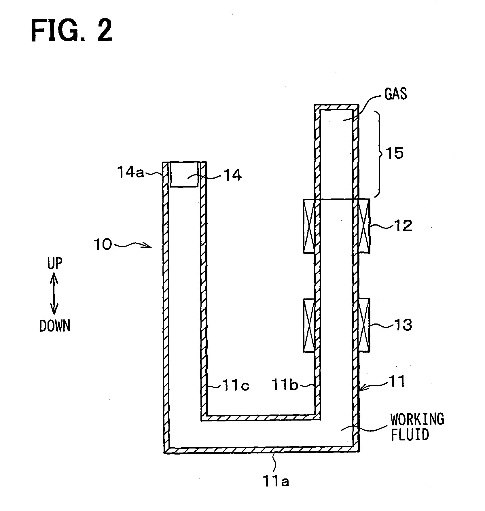
[0045] In the present invention, a steam engine is applied to a linear motor for displacing a mover 2 in a generator 1, with vibration. FIG. 1 is a schematic view of a generator set which comprises a steam engine 10 and a generator 1, and FIG. 2 is a schematic view of the steam engine 10 alone. The generator 1 according to the present invention is a linear vibration actuator which generates electromotive force by displacing the mover 2, having a buried permanent magnet, with vibration. The steam engine 10 has a fluid container 11 in which freely flowing working fluid is contained, a heater 12 for heating the fluid in the fluid container 11, a cooler 13 for cooling steam which is heated and vaporized by the heater 12, and the like.
[0046] It is preferable that the fluid container 11 be made of a heat insulation material, except for parts opposed to the heater 12 and the cooler 13. As the working fluid is water in this embodiment, the fluid container 11 is made of a stainless material....
second embodiment
[0058] In a second embodiment, as shown in FIG. 4, a regenerator 16 for exchanging heat in the working fluid is provided between the heater 12 and the cooler 13. It is preferable that the regenerator 16 have a predetermined heat capacity and a high heat transfer rate to the working fluid. In the regenerator 16, it is also preferable that thermal conductivity in the orthogonal direction of the vibration direction of the working fluid be higher than that in the vibration direction thereof. In this embodiment, the regenerator 16 is made of meshed metal laminated in the vibration direction of the working fluid, metal balls stuffed in the fluid container 11, or honeycomb metal members laminated in the vibration direction of the working fluid, and the like.
[0059] The effect of this embodiment will be hereinafter described. Of the thermal energy supplied to the working fluid by the heater 12, only the energy of steam pressure (evaporating pressure), namely the energy of expansion pressure,...
third embodiment
[0062] In a third embodiment, the cycle of an exciting force applied by the gas chamber 15 to the working fluid is out of phase with the cycle of a self-exciting vibration generated in the fluid container 11. To be more specific, as shown in FIG. 5, an inert gas chamber 15 (hereinafter called "first gas chamber 15") for directly applying the exciting force to the working fluid in the fluid container 11 and a second gas chamber 15a are coupled to each other via a throttle means such as an orifice 15b, a capillary tube or the like which generates a predetermined flowing resistance.
[0063] In this embodiment, the volume of the second gas chamber 15a is higher than that of the first gas chamber 15, so that the pressure fluctuation of the second gas chamber 15a is sufficiently small at the orifice 15b as compared with the average pressure. The cycle of the exciting force applied by the first gas chamber 15 to the working fluid is approximately one-quarter cycle out of phase with the cycle...
PUM
 Abstract
Description
Claims
Application Information