Eureka AIR delivers breakthrough ideas for toughest innovation challenges, trusted by R&D personnel around the world.

Monolayer foamed corrugated sleeve

a foamed corrugated and foamed technology, applied in the field of sleeves, can solve the problems of elongated substrates such as wire harnesses, optical fibers and fluid conduits carrying fuel, compressed gas or hydraulic fluid, and are often subjected to harsh environments, including vibration, abrasion of wiring, short circuit or failure of wiring

Inactive Publication Date: 2004-04-01
FEDERAL MOGUL WORLD WIDE
View PDF23 Cites 23 Cited by
  • Summary
  • Abstract
  • Description
  • Claims
  • Application Information

AI Technical Summary

Benefits of technology

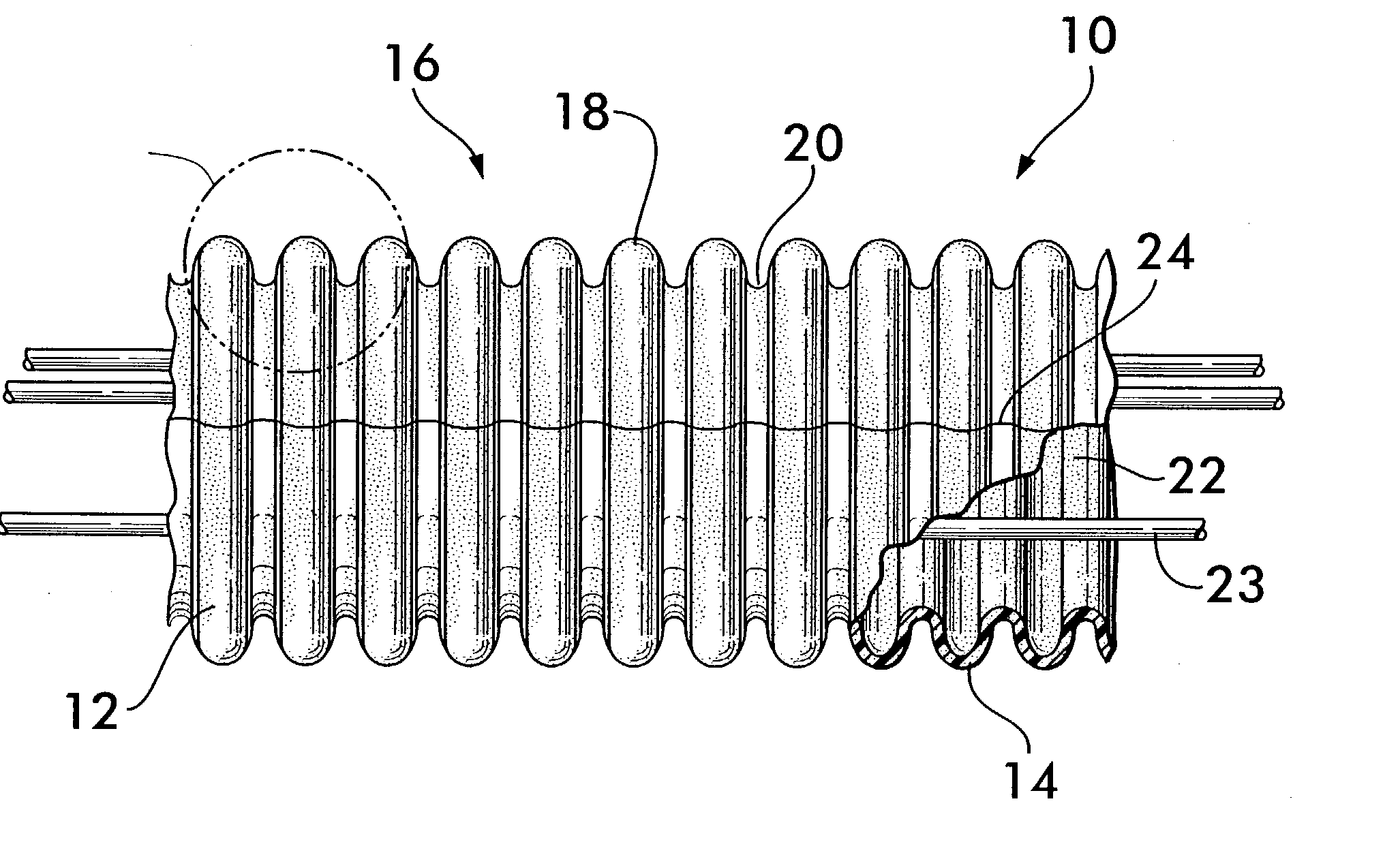
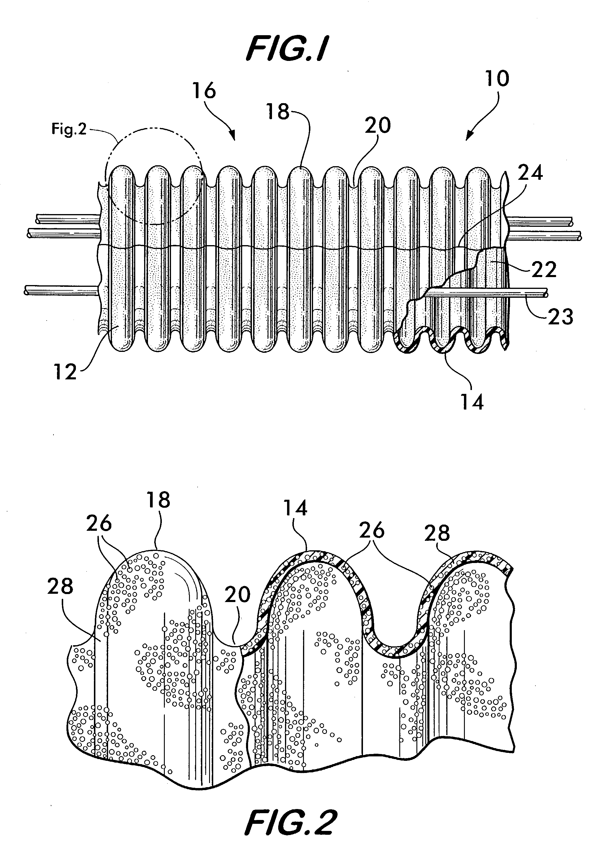
[0040] FIG. 1 shows a monolayer foamed corrugated sleeve 10 according to the invention. Sleeve 10 comprises a tube 12 having a sidewall 14 with corrugations 16 formed from a plurality of crests 18 and troughs 20 arranged one adjacent the other in alternating fashion. Corrugations 16 are preferably circumferentially oriented around tube 12 and provide radial stiffness to the tube to prevent collapse while also allowing for bending flexibility so that the sleeve 10 can be bent without kinking to follow the path of the substrates it is intended to protect. The sidewall 14 is a monolayer and surrounds a central space 22 for receiving the elongated substrates 23, for example, a wiring harness. The sidewall 14 may be a circumferentially continuous structure or it may have a slit 24 arranged lengthwise along the tube 12. Slit 24 penetrates the sidewall 14 substantially along the length of the tube and provides access to the central space 22, allowing the tube to receive substrates whose ends are inaccessible. The tube is resiliently biased so that slit 24 normally remains closed, but the sidewall 14 is also flexible allowing the slit 24 to be manually opened for access to the central space 22.
[0041] FIG. 2 shows a portion of tube 12 comprising a crest 18 and a trough 20 on an enlarged scale to illustrate the foamed construction of the sleeve 10. The foamed construction features gas-filled cellular voids 26 distributed throughout a matrix 28 comprised of various polymers and foaming agents described in detail below. The monolayer foamed construction of the tube 12 permits the sleeve 10 to provide protection to the substrates within the central space 22 from multiple different environmental threats with a single layer tube. The polymer matrix 28 affords abrasion protection, as well as protection against shock and impact forces. The well distributed cellular voids 26 provide excellent thermal protection since heat transfer across the sidewall 14 of the tube 12 is effectively inhibited by the presence of the gas-filled cellular voids throughout the matrix, which disrupt conductive heat transfer. The voids 26 also absorb sound and other vibration energy thereby providing acoustic and vibrational damping protection to the substrates. Such protection is important to avoid fatigue failure of metal substrates subjected to sustained vibrational environments such as found in automobiles and aircraft. To take best advantage of the foamed construction of the tube, it is preferred that the thickness of sidewall 14 be between about 1 / 2 mm and about 3 mm.
[0042] The polymer matrix 28 comprising tube 12 is formed from a mixture of one or more polymers and a foaming agent. The polymer component of the mixture may be a non-elastomeric thermoplastic, a combination of non-elastomeric thermoplastics, a thermoplastic elastomer, a combination of thermoplastic elastomers or a combination of non-elastomeric thermoplastics and thermoplastic elastomers. The ratio of the constituents is varied to achieve desired material properties in the sleeve 10. For example, to provide a softer tube having increased flexibility and acoustic damping properties, the ratio of thermoplastic elastomer is increased relative to the non-elastomeric thermoplastic constituent. To construct a harder, stiffer tube with improved abrasion resistance the ratio of non-elastomeric thermoplastic is increased relative to the thermoplastic elastomer. To increase the thermal insulating capacity or decrease the density of the tube, the amount of foaming agent is increased. (Damping and thermal insulation characteristics of the sleeve may also be affected by increasing or decreasing sidewall thickness.)

Problems solved by technology

Elongated substrates such as wire harnesses, optical fibers and fluid conduits carrying, for example, fuel, compressed gases or hydraulic fluid, are often subjected to harsh environments including vibration, high temperatures and abrasion.
For example, wiring passing through an engine compartment of an automobile will be subjected to engine vibration over sustained periods, causing abrasion of the wiring as it rubs against the chassis or body of the automobile.
This can lead to short circuits or failure of the wiring.
Furthermore, wiring located within the passenger compartment, for example, under the dashboard or within the doors, will also be subject to vibration from engine operation, as well as road noise transmitted through the tires and suspension system.
Such wiring will respond with sympathetic vibrations and become a source of rattle noise, annoying to driver and passengers.
Fuel or hydraulic lines passing through the engine compartment may be subjected to relatively high temperature, as well as vibration and abrasion.
Unless such lines are insulated and the vibration damped, the lines may be subjected to vapor lock, fatigue failure or accelerated corrosion and leakage due to abrasion.
Such a construction, while perhaps effectively protecting the substrate from the various adverse environments, is relatively expensive to produce because multiple layers of differing materials must be formed and joined in such a way as to hold together under the stress of the environments yet function separately and effectively to provide protection from each different threat to the integrity of the substrate.

Method used


Image

  • Monolayer foamed corrugated sleeve
  • Monolayer foamed corrugated sleeve
  • Monolayer foamed corrugated sleeve

Examples


example 2

[0047] A monolayer foamed sleeve was produced having 91 wt % ethyl vinyl acetate, 4 wt % foaming agent and 5 wt % colorant. The ethyl vinyl acetate is a thermoplastic polyethylene with 28 wt % vinyl acetate as an additive. Sleeves having this formulation exhibit very good acoustic attenuation and are soft and flexible to the touch. Higher percentages of vinyl acetate additive increase the softness and the acoustic attenuation.

example 3

[0048] A monolayer foamed sleeve was produced comprising 66.5 wt % thermoplastic vulcanizate available under the commercial name "Sarlink", 28.5 wt % polyethylene, and 5 wt % foaming agent. The resultant sleeve is soft and flexible with excellent acoustic attenuation characteristics. Because of the relatively high percentage of thermoplastic vulcanizate, the sleeve has lower abrasion resistance than sleeves made from formulations having a greater percentage of polyethylene.

example 4

[0049] A monolayer foamed sleeve was produced comprising 47.5 thermoplastic vulcanizate, 47.5 wt % polyethylene and 5 wt % foaming agent. Sleeves made according to this formulation are harder than versions having more thermoplastic vulcanizate but still maintained good acoustic attenuation properties. The abrasion resistance provided by this formulation is markedly higher than formulations having a higher percentage of thermoplastic vulcanizate.


PUM

PropertyMeasurementUnit
Thicknessaaaaaaaaaa
Pressureaaaaaaaaaa
Elastomericaaaaaaaaaa

Abstract

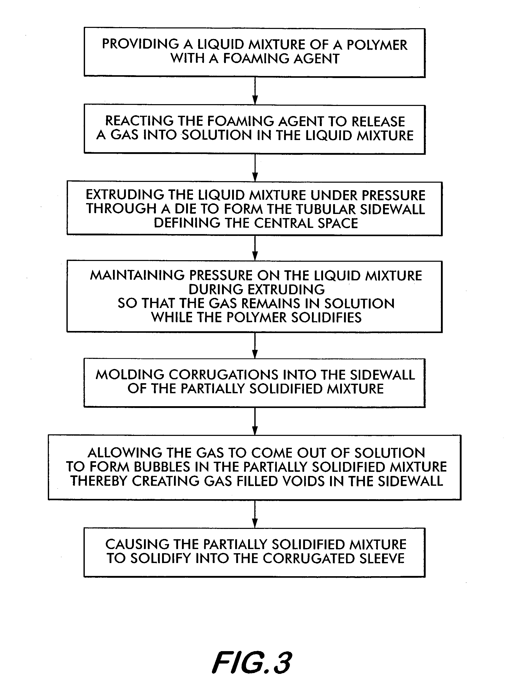
A monolayer foamed corrugated sleeve for protecting elongate substrates is disclosed. The sleeve is extruded from a polymer and a foaming agent. The polymer may be a non-elastomeric thermoplastic, a thermoplastic elastomer or a combination of the two. The sleeve is extruded from a nozzle having a cross sectional area which decreases along its length to maintain pressure on the extrudate and prevent premature foaming. The extrudate is released from the nozzle into moving mold blocks. A blow rod within the mold blocks provides gas pressure to force the extrudate against the blocks. An obturation device is mounted on the blow rod to control the gas pressure.

Description

[0001] This application is based on and claims the benefit of U.S. Provisional Application No. 60 / 385,093, filed May 31, 2002.[0002] The invention concerns corrugated foamed sleeving for providing abrasion and thermal protection, as well as acoustic damping for elongated substrates.[0003] Elongated substrates such as wire harnesses, optical fibers and fluid conduits carrying, for example, fuel, compressed gases or hydraulic fluid, are often subjected to harsh environments including vibration, high temperatures and abrasion. For example, wiring passing through an engine compartment of an automobile will be subjected to engine vibration over sustained periods, causing abrasion of the wiring as it rubs against the chassis or body of the automobile. This can lead to short circuits or failure of the wiring. Furthermore, wiring located within the passenger compartment, for example, under the dashboard or within the doors, will also be subject to vibration from engine operation, as well as...

Claims


Application Information

Patent Timeline
IPC IPC(8): B29C44/10B29C44/30B29C48/09B29C48/13B29C48/30B29C49/00B29C49/58
CPCB29C44/105B29L2023/18B29C47/0011B29C47/0023B29C47/0033B29C47/0042B29C47/126B29C49/0021B29C49/58B29K2023/06B29K2023/083B29K2023/12B29K2025/00B29K2027/06B29K2055/02B29K2077/00B29K2105/04B29K2995/0002B29K2995/0015B29C44/30B29C48/04B29C48/09B29C48/13B29C48/0012B29C48/303B29C49/0022
Inventor FATATO, FRANCIS B.STAUDT, ERIC K.
Owner FEDERAL MOGUL WORLD WIDE
Why Eureka
Eureka Blog
Learn More