Robust delay metric for RC circuits

a delay metric and circuit technology, applied in the field of standard measurement, can solve the problems of increasing gate delay, large number of cells, and complicated connections between cells, and achieve the effect of efficient performance optimization

Inactive Publication Date: 2004-04-01
GLOBALFOUNDRIES INC
View PDF6 Cites 8 Cited by
  • Summary
  • Abstract
  • Description
  • Claims
  • Application Information

AI Technical Summary

Benefits of technology

0015] It is another object of the present invention to provide such a method which can be efficiently used for performance optimization of a circuit design.
0016] It is yet another object of the present invention to provide a system and method for providing a standardized measurement of RC circuits which offer an intuitive physical interpretation of the degree of resistive shielding.

Problems solved by technology

An IC may include a very large number of cells and require complicated connections between the cells.
As process technology scales to the sub-micron regime, interconnect delays increasingly dominate gate delays.
In certain types of circuits, delays exist based on circuit topology and circuit components.
Despite its wide usage, the Elmore delay metric is known to be extremely inaccurate at times because it ignores-the resistive shielding of downstream capacitance.
Particular values may be chosen for the various circuit elements in FIG. 1, which can result in arbitrarily large errors when analyzed with the Elmore delay metric.
Errors of up to several hundred percent have been recorded when the Elmore delay metric is utilized for sub-micron technologies.
However, moment matching does not directly produce a delay approximation, but rather a reduced order response, which can be solved via nonlinear iterations.
Several of the other traditional metrics are known to be more accurate but are either CPU intensive or difficult to implement.
For example, moment matching via asymptotic waveform evaluation (AWE) is very accurate but too computationally expensive to use within a tight optimization loop.
Two-pole variants of AWE are considerably faster and recognized to be more accurate than the Elmore delay metric, but are still relatively expensive, as nonlinear solution methods such as Newton-Raphson iterations need to be run to solve the transcendental equation.
The computational cost of this approach is expensive and can have a negative impact on the overall speed of the physical optimization.
Also,-their solutions may be unstable, i.e., poles may be positive; hence special care has to be taken to ensure stability.
While this metric is useful for calculating the 50% delay, it is inadequate for other delay points.

Method used


Image

  • Robust delay metric for RC circuits
  • Robust delay metric for RC circuits
  • Robust delay metric for RC circuits

Examples


Embodiment Construction

)

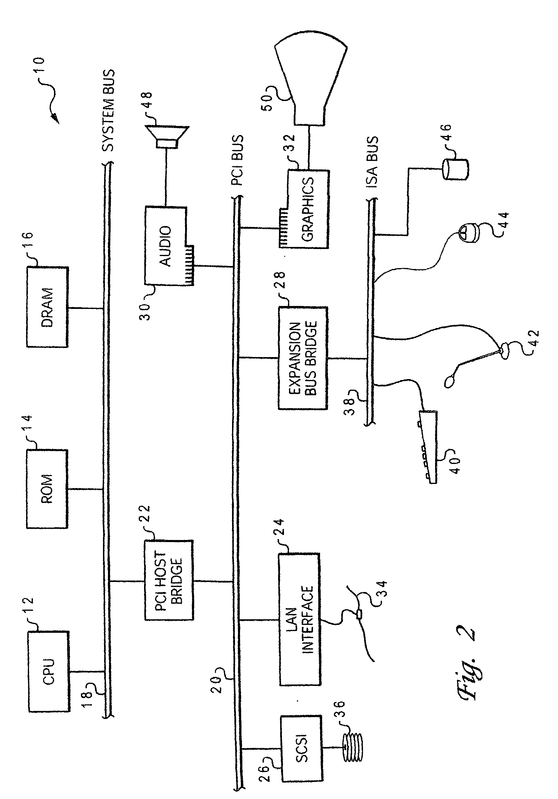
[0025] With reference now to the figures, and in particular with reference to FIG. 2, there is depicted one embodiment 10 of a computer system programmed to carry out computer-aided design of an integrated circuit in accordance with one implementation of the present invention. System 10 includes a central processing unit (CPU) 12 which carries out program instructions, firmware or read-only memory (ROM) 14 which stores the system's basic input / output logic, and a dynamic random access memory (DRAM) 16 which temporarily stores program instructions and operand data used by CPU 12. CPU 12, ROM 14 and DRAM 16 are all connected to a system bus 18. There may be additional structures in the memory hierarchy which are not depicted, such as on-board (L1) and second-level (L2) caches.

[0026] CPU 12, ROM 14 and DRAM 16 are also coupled to a peripheral component interconnect (PCI) local bus 20 using a PCI host bridge 22. PCI host bridge 22 provides a low latency path through which processor 12 ...


PUM


Abstract

Physical design optimizations for integrated circuits, such as placement, buffer insertion, floorplanning and routing, require fast and accurate analysis of resistive-capacitive (RC) delays in the network. A method is disclosed for estimating delays at nodes in an RC circuit by calculating a first and second impulse response moments of the RC circuit, and matching the impulse response moments to a Weibull distribution. Based on the match, a signal delay value is computed. The invention may thus be used to determine whether the RC circuit meets a desired optimization condition, based on the signal delay value. In the exemplary implementation, the signal delay value at a delay point is calculated by finding a percentile of the Weibull distribution corresponding to the delay point. This implementation is accurate and very efficient as it uses only two very small look-up tables.

Description

BACKGROUND OF THE INVENTION[0001] 1. Field of the Invention[0002] The present invention generally relates to standards of measurement (metrics) for characterizing features of electrical circuits, and more particularlyto a method and system which provides a delay metric for resistive-capacitive (RC) networks, such as those in an integrated circuit.[0003] 2. Description of the Related Art[0004] Integrated circuits are used for a wide variety of electronic applications, from simple devices such as wristwatches, to the most complex computer systems. A microelectronic integrated circuit (IC) chip can generally be thought of as a collection of logic cells with electrical interconnections between the cells, formed on a semiconductor substrate (e.g., silicon). An IC may include a very large number of cells and require complicated connections between the cells. A cell is a group of one or more circuit elements such as transistors, capacitors, resistors, inductors, and other basic circuit ele...

Claims


Application Information

Patent Timeline
Patent Type & Authority Applications(United States)
IPC IPC(8): G06F17/50
CPCG06F17/5036G06F30/367
Inventor ALPERT, CHARLES JAYKASHYAP, CHANDRAMOULI V.LIU, YING
Owner GLOBALFOUNDRIES INC
Why Eureka
Try Eureka