
High-vacuum valve with retractable valve plate to eliminate abrasion

a high-vacuum valve and valve plate technology, applied in the direction of valve details, valve arrangement, slide valve, etc., can solve the problems of reducing the yield of acceptable products, and affecting the quality of products produced

Inactive Publication Date: 2004-04-29
MDC VACUUM PRODS
View PDF16 Cites 76 Cited by
  • Summary
  • Abstract
  • Description
  • Claims
  • Application Information

AI Technical Summary

Benefits of technology

[0011] By eliminating all abrading contact between parts in the flow channel of the valve during the opening and closing of the valve, the valve offers a reduction in vibration, particle formation, noise, and wear, in addition to lesser friction and therefore a greater ease of movement during the opening and closing of the valve. The result is a cleaner operating environment within the vacuum chamber whose vacuum is maintained by the valve, and accordingly a higher yield of acceptable products and a longer operating life for the valve. The features of this invention can be incorporated in valves of a large range of sizes, with potentially greater benefits in terms of sealing force as the valve size increases since the number of biasing elements can be varied to suit the size of the valve plate. The number of pneumatic actuators can likewise be varied and thus the valve plate can be moved easily during opening and closing regardless of the size or shape of the valve plate or its direction of movement. The invention is therefore applicable to any high-vacuum valve that has a movable valve plate. Examples are pendulum valves, gate valves, and slide valves, as well as valves with rectangular plates, circular plates, or plates of any other shape.

Problems solved by technology

In procedures where a high-vacuum valve is opened and closed repeatedly, a valve that remains clean and performs reliably is even more critical since the opening and closing can cause wear and deterioration of the valve.
High-vacuum valves of the prior art typically contain several moving parts that encounter friction and suffer abrasion and other types of wear.
With extended use of these valves, the repeated abrasion produces debris, including metal debris that is microscopic in size.
The presence of debris in a valve inevitably lowers the yield of acceptable products produced from equipment in which the valve is used.
The moving parts often cause vibration as well, which further adds to the risk of low product quality.
The need to discard products that do not meet specifications and to replace worn valves adds considerably to the manufacturing costs.
The orientation of a high-vacuum valve is often a compromise between maintaining the seal integrity under these circumstances and prolonging the life of the valve.
This complicates the construction of the valve.

Method used


Image

  • High-vacuum valve with retractable valve plate to eliminate abrasion
  • High-vacuum valve with retractable valve plate to eliminate abrasion
  • High-vacuum valve with retractable valve plate to eliminate abrasion

Examples


Embodiment Construction

[0024] While this invention is susceptible to a large number of implementations, embodiments, and configurations, the basic elements of the invention and how they can be implemented in different valve types and constructions will be best understood from a detailed examination of specific embodiments. Such embodiments are shown in the attached drawings and explained below.

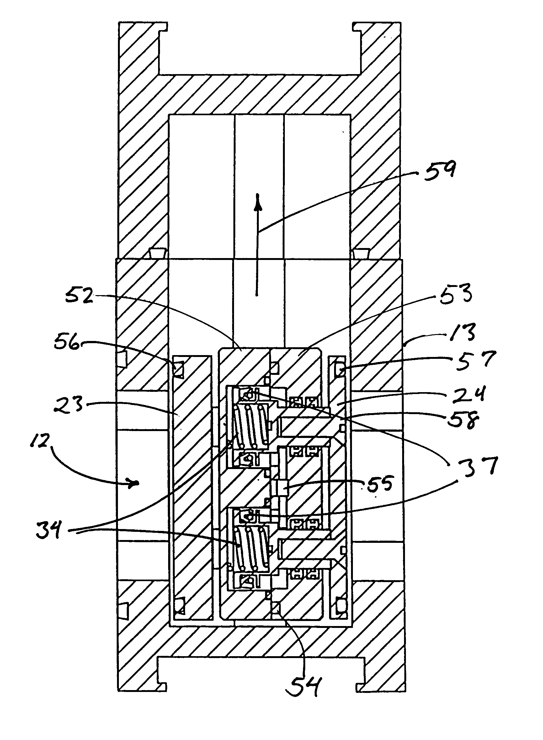
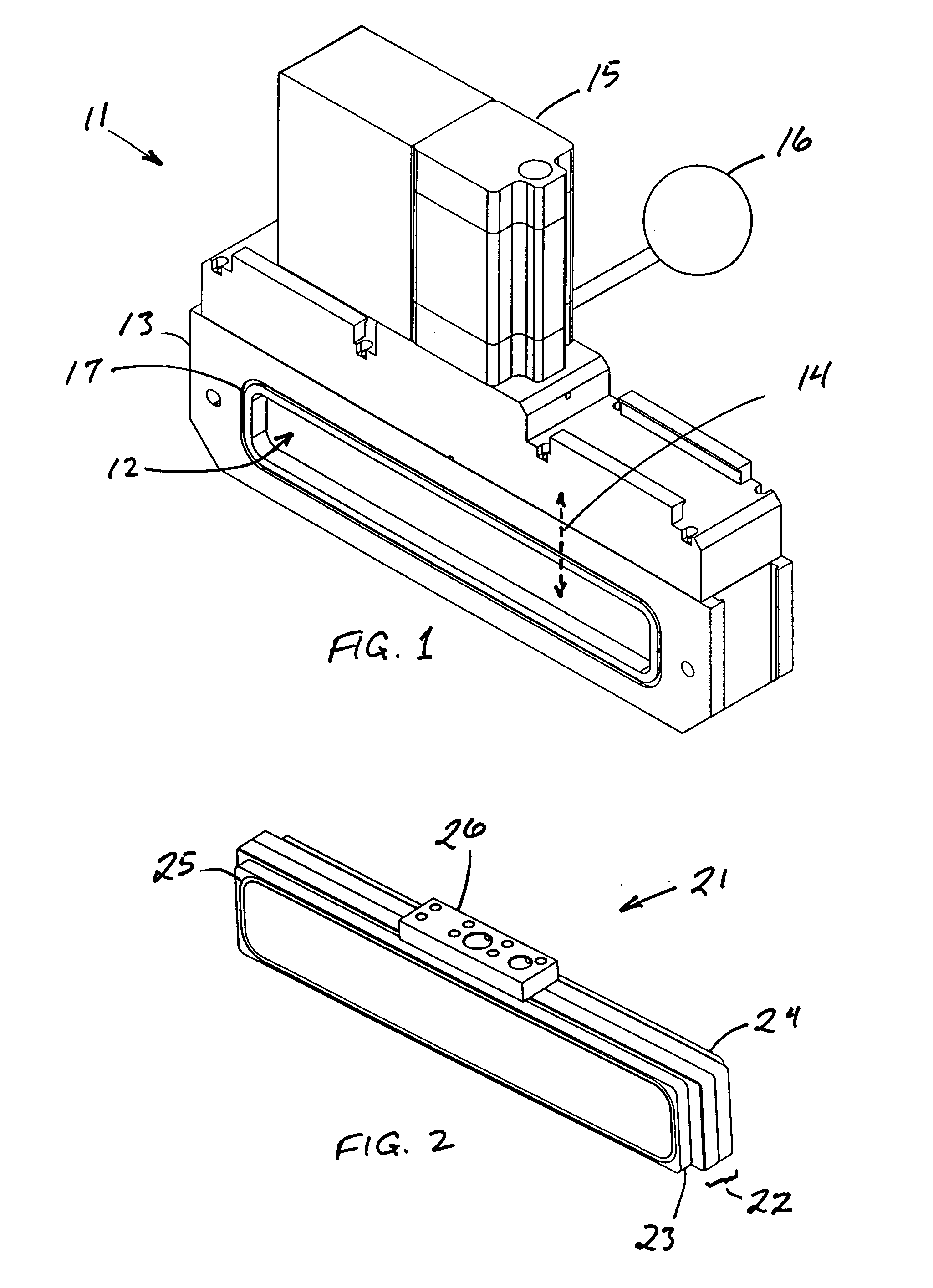
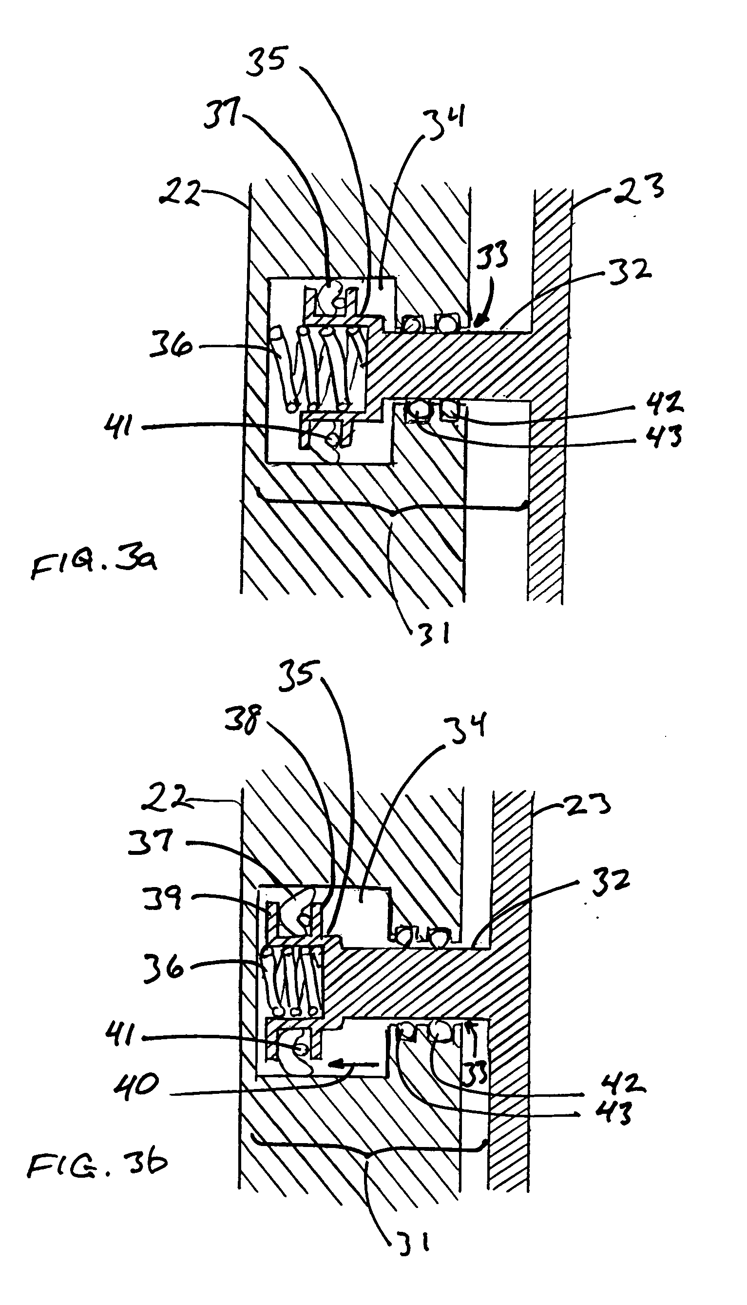
[0025] The valve shown in FIG. 1 is a gate valve 11 with a flow channel 12 of rectangular cross section. The valve plate, not visible in this view, is inside the valve body 13 and opens and closes by moving up and down within the valve body in the direction shown by the dashed arrow 14. A tower 15 extends above the valve housing to contain circuitry, flow channels supplying pressurized air to the pneumatic actuators (which are shown in subsequently numbered drawings and explained below), actuator valves for turning the pressurized air on or off, and other components that drive and control the movement of the valve p...


PUM


Abstract

A valve achieves a high-vacuum seal and opens and closes with no sliding or otherwise abrading contact between the sealing plate and the valve seat, while maintaining pressure of the plate against the valve seat in the event of a failure in the valve actuation mechanism. These results are attained by use of a composite valve plate that includes a sealing plate joined to a support block through a retractable resilient connector. During retraction, the sealing plate is drawing close to the block by a pneumatic actuator internal to the composite valve plate, the actuator arranged to oppose and overcome a mechanical resilient element also contained within the valve plate that urges the sealing plate outward from the support block to effect the seal when the actuator is not engaged.

Description

[0001] This application claims benefits from U.S. provisional patent application No. 60 / 397,917, filed Jul. 22, 2002, for all purposes legally served thereby. The contents of provisional patent application No. 60 / 397,917 are hereby incorporated herein by reference in their entirety.[0002] 1. Field of the Invention[0003] This invention resides in the field of high-vacuum valves and the structural features that are designed to prolong the useful life of such a valve and to eliminate or reduce the risk of introducing debris into procedures where such valves are used.[0004] 2. Description of the Prior Art[0005] High-vacuum valves are critical equipment in a wide variety of procedures, ranging from analytical procedures to manufacturing processes. Particle physics experiments, x-ray tomography procedures, manufacturing processes for high-precision electronic components, and procedures involving the application of coatings by chemical vapor deposition are just examples of the many applica...

Claims


Application Information

Patent Timeline
IPC IPC(8): F16K3/18F16K3/28F16K25/00F16K51/02
CPCF16K51/02F16K3/18
Inventor CONTIN, JOSE L.ULEA, NELI
Owner MDC VACUUM PRODS
Learn More