Color video projection system employing reflective liquid crystal display devices

a liquid crystal display and video projection technology, applied in the direction of picture reproducers using projection devices, non-linear optics, instruments, etc., can solve the problems of high component cost, projection lens requires a long back working distance, stress birefringence, etc., to achieve less cost, less weight, and compact

Inactive Publication Date: 2004-05-06
DISPLAY VECTORS LLC
View PDF8 Cites 16 Cited by
  • Summary
  • Abstract
  • Description
  • Claims
  • Application Information

AI Technical Summary

Benefits of technology

0022] This invention is advantageous because it enables constructing a reflective LCD light valve-based multimedia projector that is lighter weight, more compact, potentially less costly, and of simpler optical design than prior prism based projectors. The system is lighter because no bulky prisms are required, more compact because it requires only one dichroic filter and a polarizing beam splitter, and less costly because the optical component count is low and there are no prisms.
0023] This invention is further advantageous because it allows construction of a projector that is less subject to contrast degradation due to birefringence problems caused by residual or thermally induced stresses.

Problems solved by technology

This architecture is disadvantageous because it requires sophisticated optical coatings and non-standard prism angles and has skew ray depolarization caused by the PBS cube prism, stress birefringence caused by long path lengths in glass elements, and considerable weight due to the bulky prisms.
This architecture is disadvantageous because of stress birefringence caused by the large path lengths in glass, skew ray depolarization caused by the PBS cube prism, and considerable weight due to the bulky prisms.
This architecture is disadvantageous because of considerable aggregate weight of the three PBS cube prisms and the X-cube prism, high component cost and complexity, stress birefringence, skew ray depolarization in the PBS cube prisms, and a large footprint created by the separated color paths.
This architecture is disadvantageous because the PBS cube prism is bulky, heavy, has stress birefringence, and skew ray depolarization, and the projection lens requires a long back working distance.
This architecture is disadvantageous because it has an unduly high-profile, two-level form factor and requires an proprietary, asymmetrical, off-axis projection lens.

Method used


Image

  • Color video projection system employing reflective liquid crystal display devices
  • Color video projection system employing reflective liquid crystal display devices
  • Color video projection system employing reflective liquid crystal display devices

Examples


first embodiment

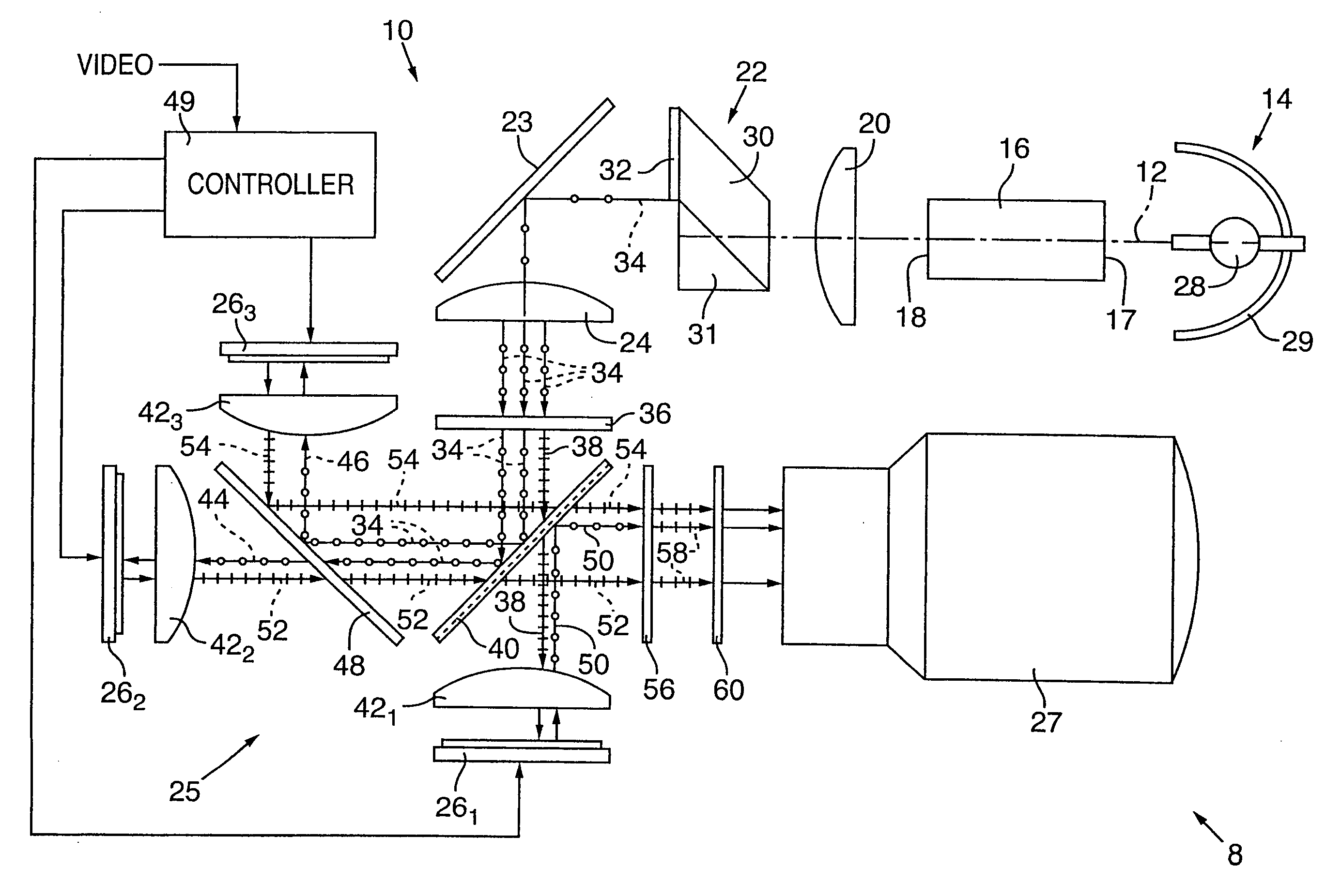
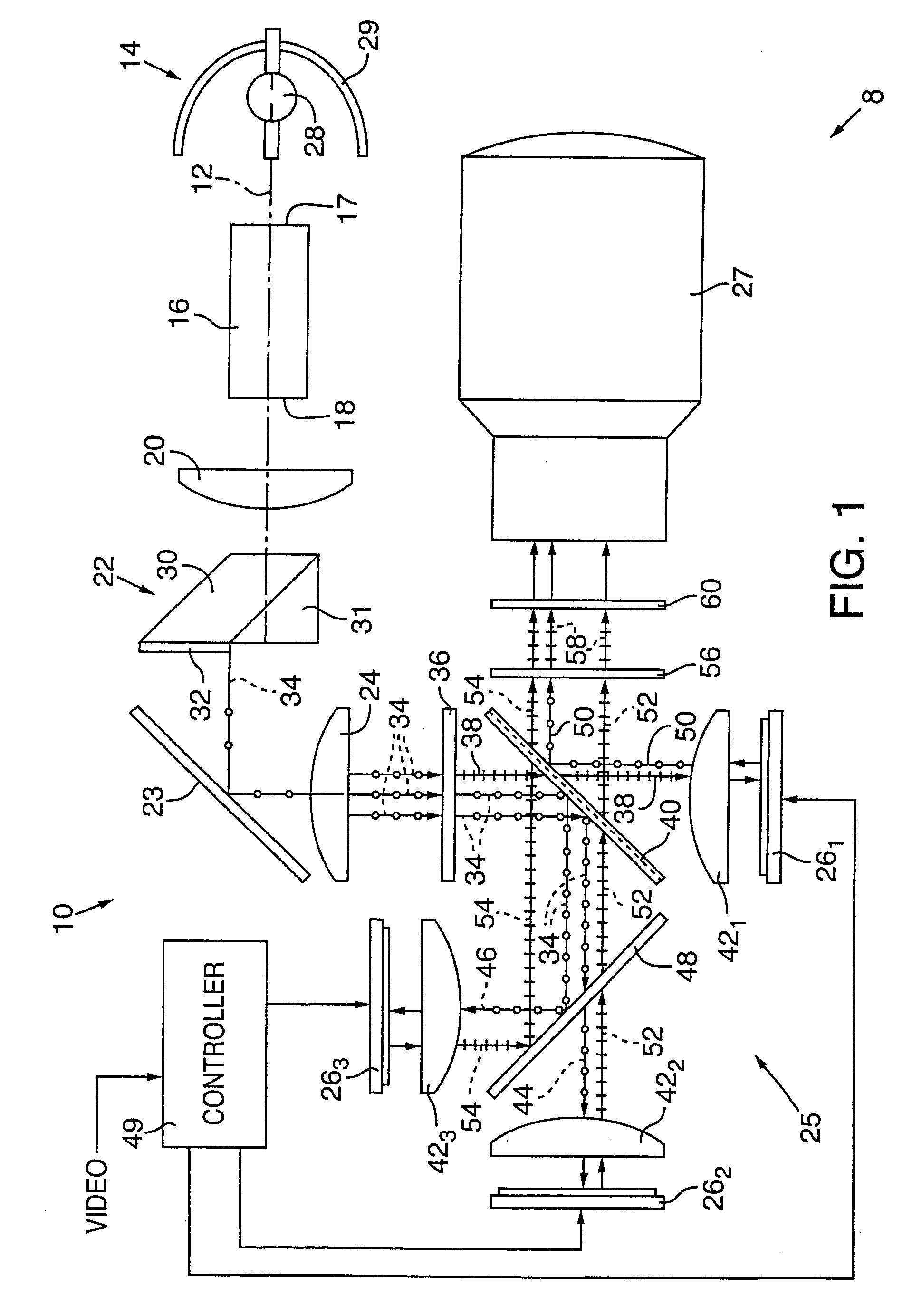
[0025] FIG. 1 is a simplified pictorial plan view of a multimedia projector showing a projector optical system of this invention.

second embodiment

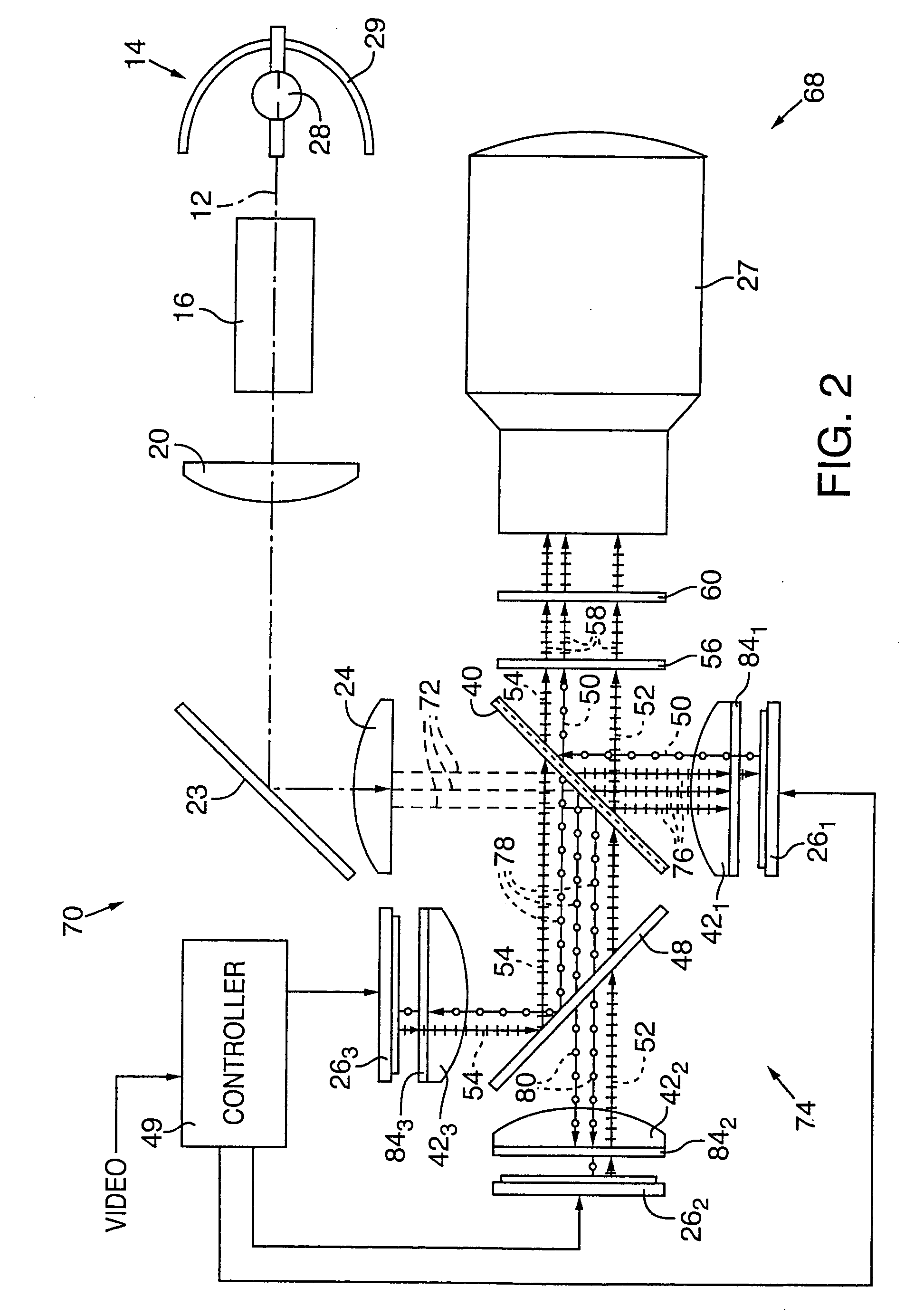
[0026] FIG. 2 is a simplified pictorial plan view of a multimedia projector showing a projector optical system of this invention.

[0027] FIG. 1 shows an image projector 8 having an optical system 10 designed in accordance with a first embodiment of this invention and enclosed in and supported by a housing (not shown). Optical system 10 is constructed along an optical axis 12 and includes a light source 14; a light pipe optical integrator 16 having an inlet end 17 and an outlet end 18; a first positive lens 20; a polarization conversion prism assembly 22; a fold mirror 23; a second positive lens 24; a three-path reflective LCD assembly 25 that includes first, second, and third liquid crystal displays ("LCDs") 26.sub.1, 26.sub.2, and 26.sub.3 (collectively "LCDs 26"); and a telecentric-type projection lens 27. LCDs 26 are preferably about 15 millimeter (0.6 inch), reflective LCOS light valves employing twisted neumatic liquid crystal material, which is optically active. Of course, othe...


PUM


Abstract

An image projector (8, 68) includes a light source (14) that illuminates a three-path reflective LCD assembly (25, 74) that produces images for projection by a projection lens (27). The light source produces S-polarized light rays that are received by a spectrally selective wave plate (36) that changes a first wavelength range of light to P-polarized light rays (34) and transmits without polarization change second and third wavelength ranges of light. A plate-type transflective polarizing beam splitter (40) transmits the P-polarized first wavelength range light rays and reflects S-polarized second and third wavelength range light rays (34). The P-polarized first wavelength range light rays transmit through a field lens (421) and impinge on a first reflective LCD light valve (261). The S-polarized second and third wavelength range light rays strike a pleochroic filter (48), which divides them into second and third wavelength range light rays (44, 46) that propagate through field lenses (422, 423) and impinge on respective second and third LCD light valves (262, 263). The light rays impinging on dark state pixels on the first LCD light valve are reflected without polarization direction change and return toward the light source along their original paths. However, the light rays impinging on illuminated state pixels on the first LCD light valve are reflected with a 90° change in polarization direction and are reflected toward the projection lens by the transflective polarizing beam splitter. The light rays impinging on illuminated state pixels on the second and third LCD light valves are reflected with a 90° change in polarization direction, are recombined by the pleochroic filter, and transmit through the transflective polarizing beam splitter toward the projection lens.

Description

TECHNICIAN FIELD[0001] This invention relates to color video projection display systems and more particularly to optical pathway components for use in projection systems employing reflective liquid crystal on silicon ("LCOS") light valves.[0002] Multimedia projection systems have become popular for purposes such as conducting sales demonstrations, business meetings, and classroom training. In typical operation, multimedia projection systems receive analog video signals from a personal computer and convert the video signals to digital information to control one or more digitally driven light valves. Depending on the cost, brightness, and image quality goals of the particular projector, the light valves may be of various sizes and resolutions, be transmissive or reflective, and be employed in single or multiple light path configurations.[0003] Recently, more optimal sets of multimedia projector characteristics have been achieved by employing reflective LCOS light valves. There are fiv...

Claims


Application Information

Patent Timeline
Patent Type & Authority Applications(United States)
IPC IPC(8): H04N9/31
CPCG03B21/14H04N9/3197H04N9/3167H04N9/3105G03B21/005G03B21/2073
Inventor STAHL, KURTGOHMAN, JEFFREY A.
Owner DISPLAY VECTORS LLC
Why Eureka
Try Eureka