
On-line monitoring and/or control of headspace in a fluid bed reactor system

Inactive Publication Date: 2004-06-03
CHR HANSEN AS
View PDF2 Cites 0 Cited by
  • Summary
  • Abstract
  • Description
  • Claims
  • Application Information

AI Technical Summary

Benefits of technology

[0015] Particularly, it is an objective of the present invention to provide a method which makes it possible to minimise the headspace volume of carrying medium substantially void of fluidised particles in the fluid bed reactor system by monitoring a particle density gradient formed within a second volume of the carrying medium comprising a bed of fluidised particles.
[0016] It is a new and inventive feature of the present invention that it makes use of a recently found feature of fluid bed systems, that the fluid bed comprises a particle density gradient under all flow conditions, which provides a useful basis for dynamically detecting and / or controlling the dynamics of the system.
[0023] The up-flow system may be equipped with a device, which can control the volume of the reactor system. Such controlling devices may include a floating body equipped with an outlet. A floating body is preferably made of a material, which permits it to float on top of the headspace volume. The advantage of such a floating outlet is the possibility to reduce the headspace volume of the system by allowing the adjustment of the headspace in relation to expansion of the bed particles. Hence, the floating outlet allows for a more flexible reactor system. In the fluid systems large quantities of liquid is used. Reducing the headspace volume leads to a more pure and concentrated and thus, a more valuable product.
[0034] Generally, fluid bed systems such as fluidised and expanded bed systems are operated under flow conditions resulting in an even and smooth distribution of fluidised particles in the fluid bed and substantially without turbulence in the fluid bed of particles. It is however contemplated that a more turbulent flow may be applied to the system still forming a particle density gradient, which can be used for detection and control. It is contemplated that the flow applied to the fluid bed reactor system is often a mixture of a laminar flow and a turbulent flow.

Problems solved by technology

In more conventional systems such other materials could cause problems manifested by an increase in the pressure drop across the fluid bed and the formation of a plug of trapped solids at the inlet of the bed.
This is, however, an unreliable method as gas bubbles and solid particles trapped in the headspace volume may disturb the signals.
The presence of gas bubbles will cause the signal to disappear and solid particles in the headspace volume will give rise to noise signals.
Such a signal does not allow for a dynamic control of the expansion, as there will be no information on how far the bed surface is from any of the levels, and accordingly no possibility of adjusting the flow velocity to this situation.
In an SU Inventors Certificate No. 1696886 it is recognised that the interface between the particle bed and the headspace may be inhomogeneous and thus difficult and unreliable to use for control of the system dynamics.
This approach has to be repeated for each individual system that is to be controlled and a great amount of time has to be spent on calibrating the system before use.
Hence, this patent application provides no method for dynamically adjusting the flow according to the determined density.
Accordingly, the prior art discloses unreliable or cumbersome ways of controlling the expansion of a fluid bed reactor system.

Method used


Image

  • On-line monitoring and/or control of headspace in a fluid bed reactor system
  • On-line monitoring and/or control of headspace in a fluid bed reactor system
  • On-line monitoring and/or control of headspace in a fluid bed reactor system

Examples


example 1

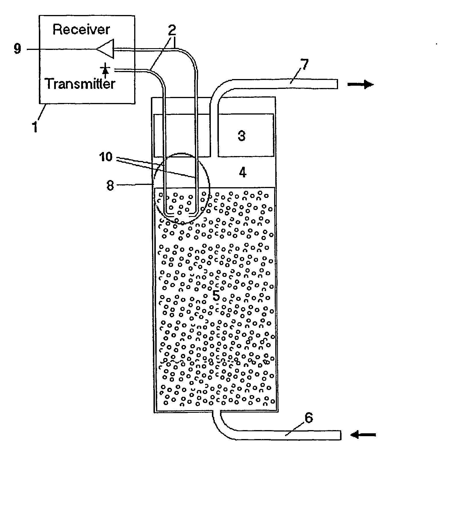
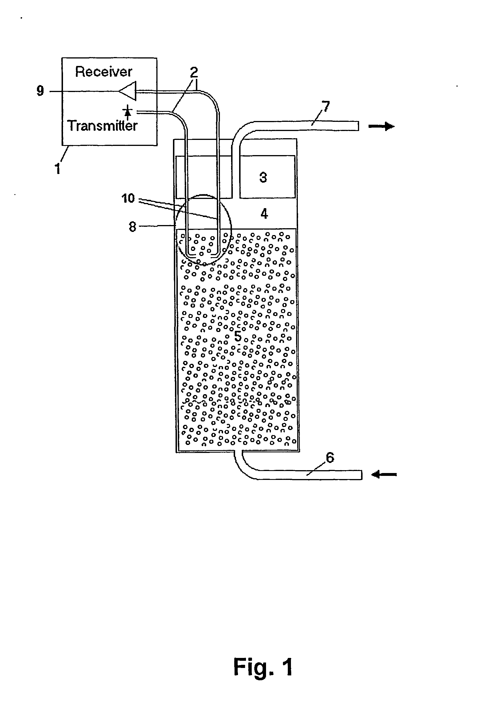
[0045] The fluid bed reactor system is illustrated in FIG. 1 and consists of a cylindrical column in which the particles suspended in the carrying medium are contained. The medium 6 is pumped into the bottom of the column whereby the volume of the particles suspended in the medium is expanded. The medium is pumped out of the column through an outlet 7 mounted on a floating body 3. Hereby, two volumes are formed in the column: One fluid bed phase 5 containing particles suspended in the medium and one phase 4 substantially void of particles but containing media (headspace).

example 2

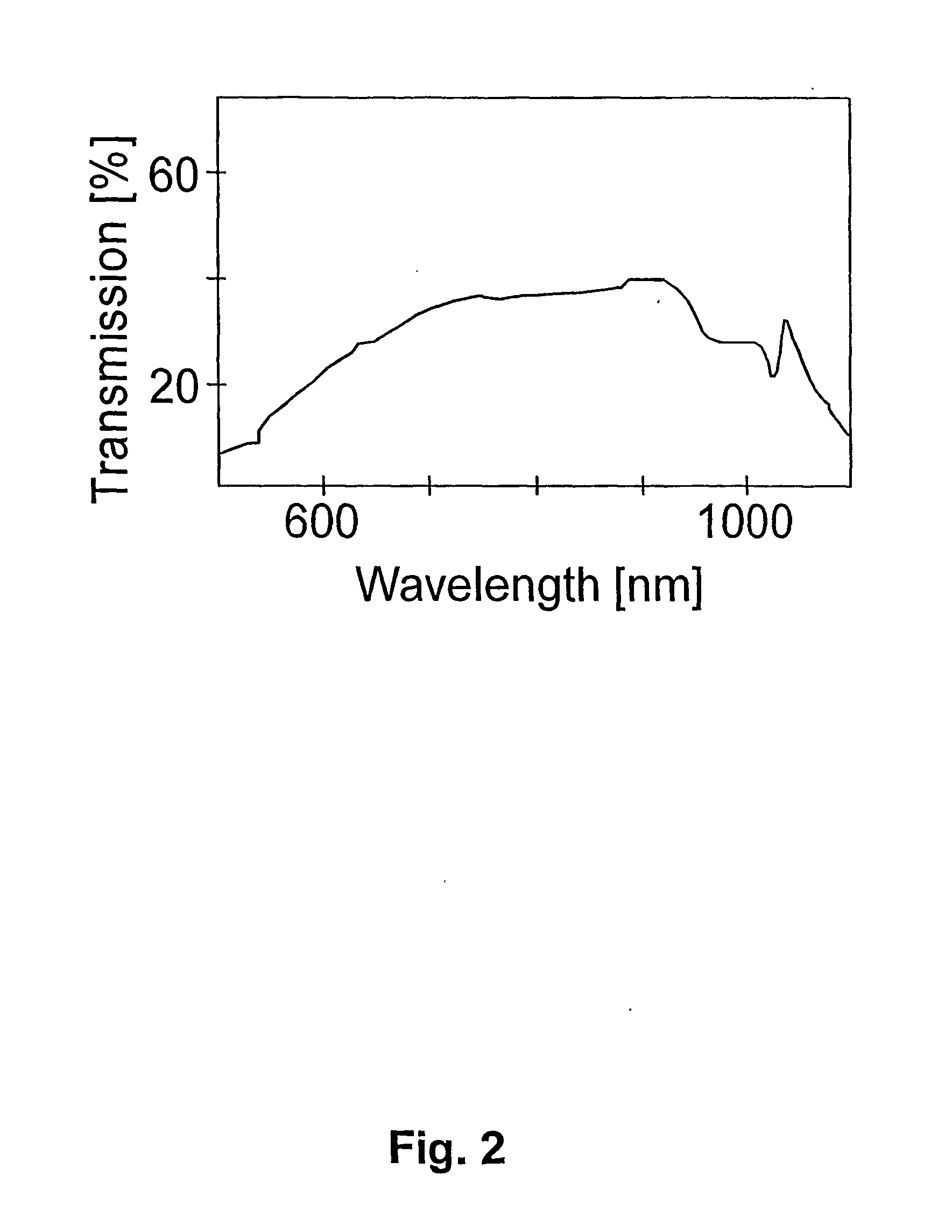
[0046] Monitoring of the interface between the headspace and the fluid bed of particles suspended in the medium does not allow for dynamic control of the fluid bed system, as the signal would be an on / off signal indicating whether the interface was above or below the level of detection. However, it was found that an electromagnetic radiation signal traversing the fluid bed was not totally extinguished but actually showed a significant signal. Furthermore, it was found that this signal was dependent on the position of the sensor in respect to the interface between the headspace and the fluid bed of particles suspended in the medium. Thus, it was possible to detect particle density gradients within the fluid bed of particles, which could be used as a tool in controlling of the expansion of the system. It was expected that the macrostructure of the particles e.g. size, shape, material etc. and material in the carrying medium would effect the signal. Therefore a transmitting signal at f...

example 3

[0054] The sensor system as described and operated in Example 2 was used to verify the existence of a particle density gradient in a fluid bed of particles. The optical transmitter 1 produced a monochromatic and incoherent and pulse modulated beam of light at a frequency of 660 nm. The receiver 1 demodulated the signal and formed an analogue signal 9 corresponding to the received signal. The transmitter and receiver were physically contained in the same unit.

[0055] The analogue output signal 9 from the receiver was proportionate to the power of the received signal relative to the power of the transmitted signal. Alternatively, the intensity, luminosity or fluence of the received signal can be measured, depending on the specific set-up. The mixture of fluid bed particles and the carrying medium causes the difference in transmitted and received signal.

[0056] The sensor head 8 was mounted on the floating body 3 so that the ends of the stainless tubes 10 were at a given distance below t...


PUM

PropertyMeasurementUnit
Flow rateaaaaaaaaaa
Sizeaaaaaaaaaa
Densityaaaaaaaaaa

Abstract

A novel method is provided for detection and / or control of the dynamics, e.g. the headspace, in a fluid bed reactor system based on detecting a pre-determined particle density gradient formed within a spatially confined fluid bed of fluidised particles in a carrying medium. More specifically, a method is provided where transmitting means and receiving means are used for detecting the pre-determined particle density gradient formed and subsequently the signal is used for activating or deactivating flow controlling means whereby the dynamics of the system can be controlled.

Description

[0001] The present invention relates in its broadest aspect to the field of detecting and / or controlling the dynamics e.g. the headspace, of a system comprising a spatially confined fluid bed of particles fluidised in a carrying medium. More specifically there is provided a novel method where transmitting means and receiving means are used for detecting a pre-determined particle density gradient formed within the fluid bed of fluidised particles whereby the dynamics of the system can be controlled.TECHNICAL BACKGROUND AND PRIOR ART[0002] A large number of target molecules i.e. compounds and other materials e.g. peptides, vitamins, hormones, lipids, proteins, enzymes, membranes, cells and the like and compounds from e.g. a petroleum or coal source can be reacted, separated and / or purified using chromatographic techniques. Such techniques include ion-exchange chromatography, reverse phase chromatography, hydrophobic interaction chromatography, affinity chromatography and mixed mode ch...

Claims


Application Information

Patent Timeline
IPC IPC(8): B01D15/18B01J8/18B01J8/24G01N30/52
CPCB01D15/1807B01D2215/021B01J8/1809G01N2030/524B01J2219/00195B01J2219/00213B01J2219/00231B01J2208/00584
Inventor MELDGAARD, MORTENHERBSLEB, PETERBJORHOLM, JACOBHOULBERG, ULF
Owner CHR HANSEN AS
Features
  • Generate Ideas
  • Intellectual Property
  • Life Sciences
  • Materials
  • Tech Scout
  • Unparalleled Data Quality
  • Higher Quality Content
  • 60% Fewer Hallucinations
Learn More