
Three-dimensional microfluidics incorporating passive fluid control structures

a microfluidic and fluid control technology, applied in the field of three-dimensional microfluidics incorporating passive fluid control structures, can solve the problems of affecting the flow rate of fluid, so as to achieve simple, effective and versatile control of fluid movemen

Inactive Publication Date: 2004-06-10
BIOMICRO SYST
View PDF55 Cites 304 Cited by
  • Summary
  • Abstract
  • Description
  • Claims
  • Application Information

AI Technical Summary

Benefits of technology

[0027] It is a further object of the invention to provide a three-dimensional microfluidic device with the capability of simple, effective and versatile control of fluid movement within the device. This is accomplished by the use of pressure-driven flow in combination with valves to direct fluid flow. Valves utilized in the invention do not require complex mechanical structures to be constructed in the device.
[0028] Another object of the invention is to provide a method of sealing layers of a multi-layered microfluidic device in a reliable, leak-free manner.
[0029] Yet another object of the invention is to provide a leak-free method of sealing layers of a multi-layered microfluidic device that is also releasable. This makes it possible to disassemble the device after use to permit the reuse of portions of the device, disposal of other portions of the device, and retrieval of materials contained within device.
[0032] Still another object of the invention is to provide a multi-layered microfluidic device capable of mating to conventional substrates such as slides or microtiter plates. This provides the advantage of integrating microfluidic pre- and post-processing capabilities with reactions carried out on or in conventional substrates with microvolumes of fluid.

Problems solved by technology

In contrast, to form structures that overlap or have varying altitudes in a bulk substrate, it is necessary to form at least one of the structures in the interior of the bulk substrate, which is considerably more difficult than forming surface structures.
In other cases, it may be theoretically possible to form a particular microfluidic circuit in a single layer, but undesirable from a practical standpoint because the size of the device and the length of the microfluidic channels would have to be too large.
), in many cases even a two-layer device may be undesirable from a practical standpoint for the reasons noted above.
In practice, 3-dimensional or multi-layer microfluidic systems are more complicated, more expensive, and more prone to failure than 2-D or single layer systems.
The major complications in the fabrication of multi-layered microfluidic systems arise in the alignment and sealing of the various layers together.
Large geometry systems, where the features may be on the order of 1 mm or more, present fewer problems with regard to alignment However, in systems with very small features, particularly small connecting vias on the order of 100 .mu.m or less, alignment is a considerable problem.
Providing a leak-free seal between multiple layers remains a challenge.
The challenge then becomes finding an adhesive that forms an effective seal, and that can also be released when desired, but not before.
Controlling the movement of fluids within a microfluidic device is an essential aspect of virtually any microfluidic device, but is more difficult to implement in more complex microfluidic circuits.
Microscale active valves, however, are relatively complicated and difficult to construct, even in 2- or 21 / 2-D systems.
Hydrophilic capillary valves are commonly used in microfluidic devices, but tend to be unstable.
A hydrophilic capillary valve in a hydrophilic material creates only a local minimum in hydrostatic pressure, and can be easily breached by fluid flow momentum or small disturbances, causing loss of flow control.
However, a well thus formed will not have much depth, and thus may have a lower than desired volume, or larger than desired surface-volume ratio.
If the air cannot escape, it will cause a backpressure that opposes further advancement of the fluid.
However, the use of hydrophobic air ducts is particularly advantageous since air escape is permitted, but fluid flow through air ducts is restricted.
If multiple thin layers are used such that fluid circuit structures are cut through entire layer thicknesses, the "island" of material surrounded by the main channel and the side channel will be unsupported, which may complicate manufacturing.
Because such components are typically more expensive to manufacture than basic microfluidic circuitry, it is preferred that such components are incorporated into a portion of the device that can be reused.

Method used


Image

  • Three-dimensional microfluidics incorporating passive fluid control structures
  • Three-dimensional microfluidics incorporating passive fluid control structures
  • Three-dimensional microfluidics incorporating passive fluid control structures

Examples


example 2

[0097] FIG. 4 depicts a device that can be used for pre-processing sample and hybridization solutions for probe-oligo or probe-cDNA hybridizations on microarrays. Such a device could be used to identify suitable hybridization conditions prior to running a series of microarray hybridizations. Multiple hybridizations are performed on a single array under different conditions to minimize the slide-to-slide variation observed in microarray hybridization reactions, which obscures subtle differences in these gene expression experiments crucial in the drug discovery process. Sample can be dye-labeled and combined with hybridization solution in the device. Preparation of hybridization solutions having different concentrations of sample or other components can be carried out in the device. Salt buffer (SSC) and formamide are typical components of the hybridization solution that may be adjusted to maximize hybridization sensitivity. This is especially important when studying low abundance gen...

example 3

[0102] FIG. 3A depicts a three-dimensional microfluidic device 300 that performs serial dilution of a sample and delivers sample solutions and a series of appropriate reagents / reactants to a diagnostic surface 303 for the performance of a multiplexed immunoassay, e.g., an Enzyme Linked Immuno-absorbent Assay or "ELISA". The microfluidic circuit is designed to interface with a diagnostic surface 303 such as a slide or microtiter plate having small regions 3181-318e containing immobilized capture antibodies specific for a analyte(s) of interest The device has been simplified to more clearly illustrate its principles of operation. In practice, diagnostic surface 303 could contain a larger number of regions bearing capture antibodies, for example in an array made up of multiple rows, as opposed to a single row as depicted here. Device 300 would have a correspondingly larger number of microfluidic circuits to deliver sample and reagents to the larger number of regions bearing antibodies....


PUM


Abstract

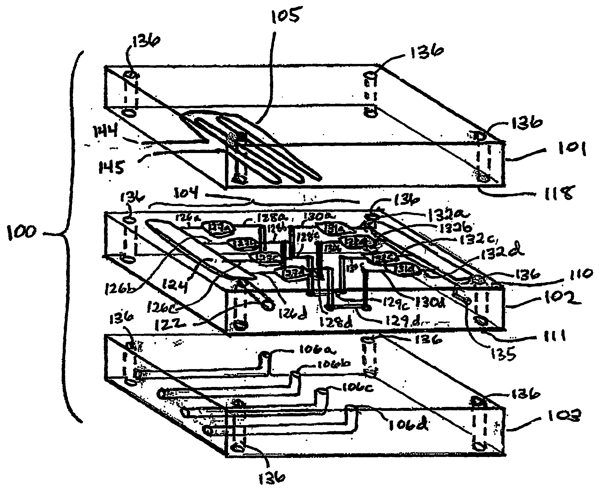
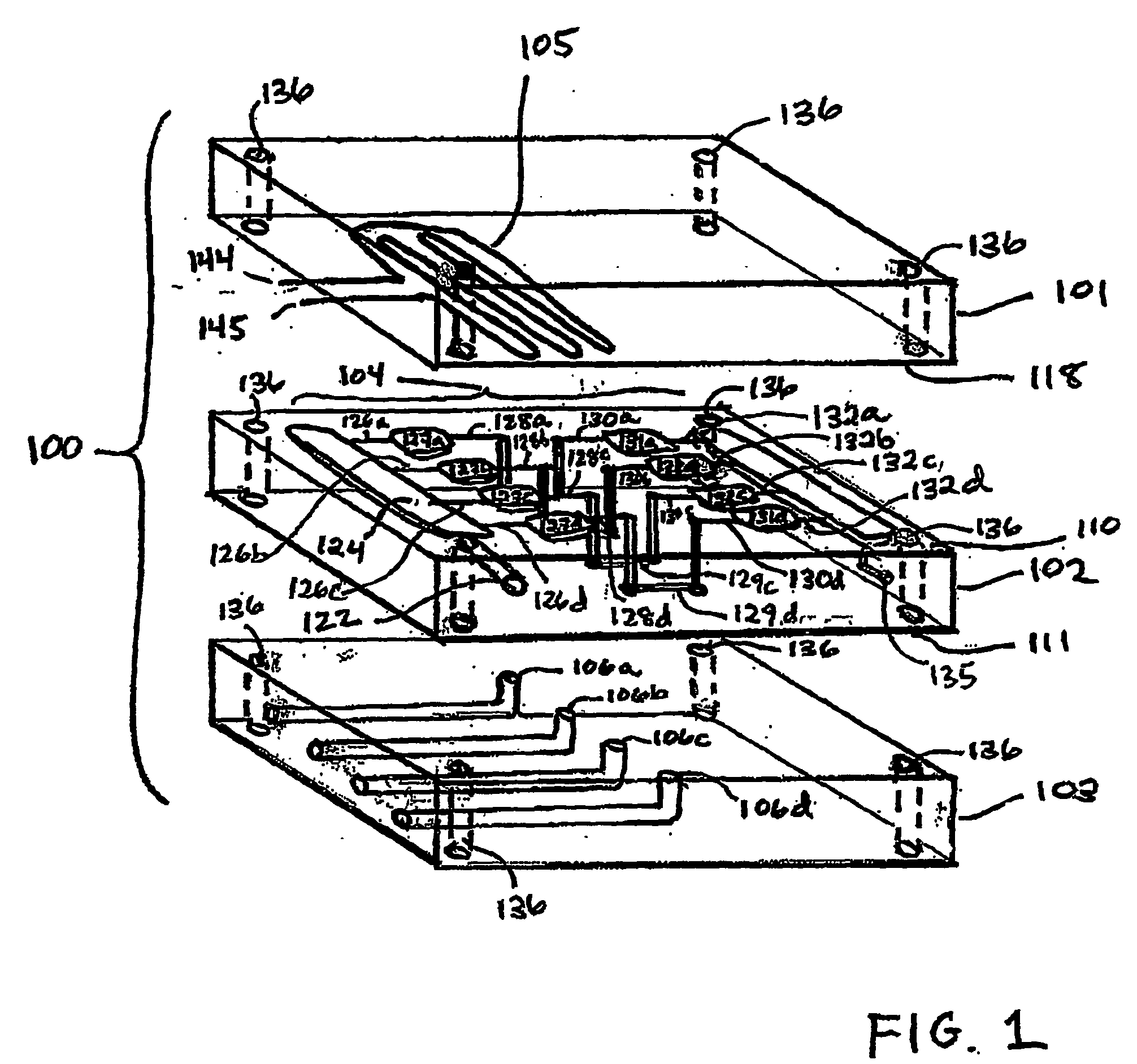
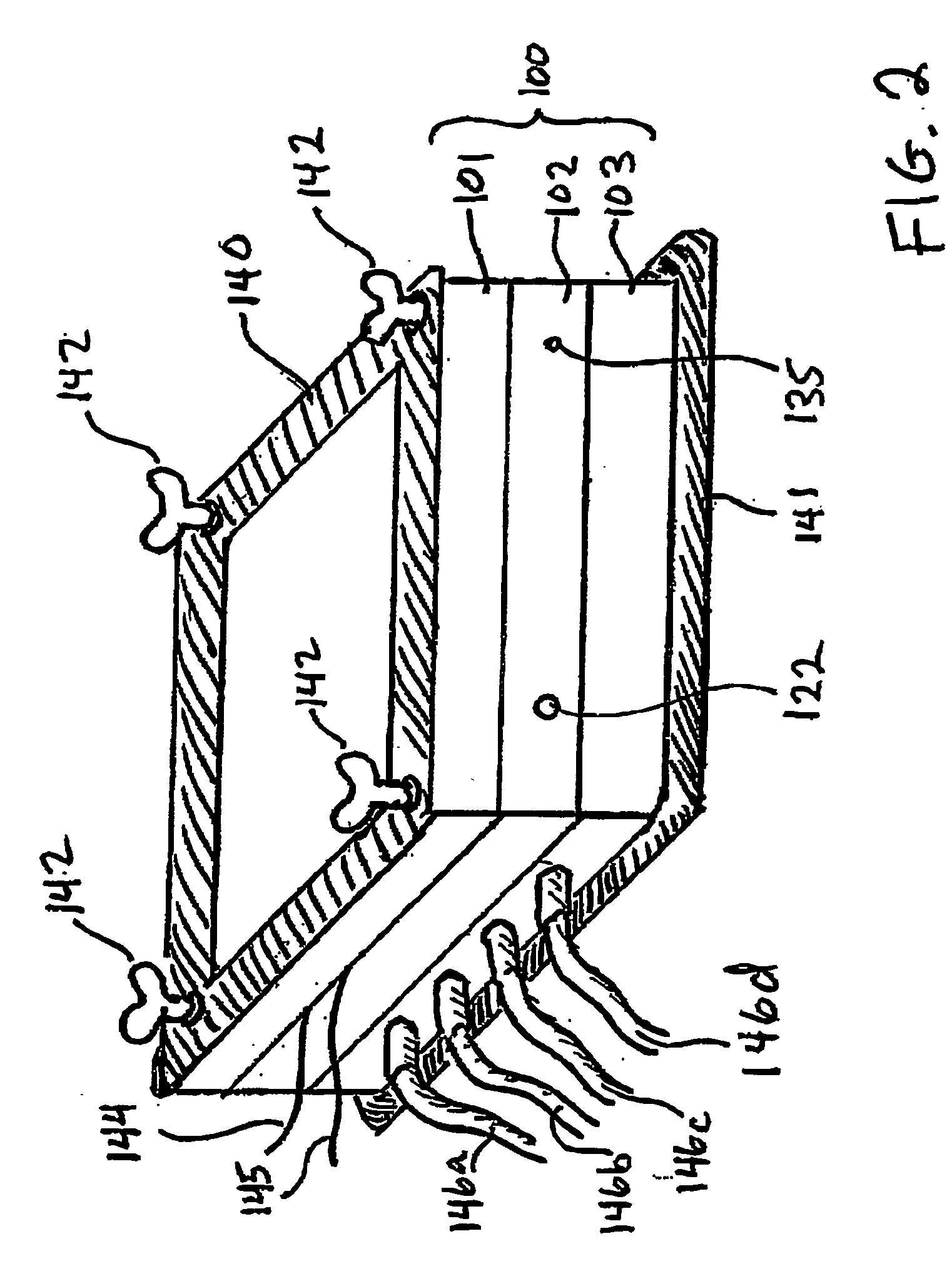
A three-dimensional microfluidic device (100) formed from a plurality of substantially planar layers (101, 102, 103) sealed together is disclosed

Description

[0001] In the United States, this application is a Continuation-in-Part of U.S. patent application Ser. No. 09 / 967,402, filed Sep. 28, 2001, which is a continuation of U.S. patent application Ser. No. 09 / 417,691, filed Oct. 13, 1999, now issued as U.S. Pat. No. 6,296,020 on Oct. 2, 2001, which claimed priority to U.S. Provisional Application 60 / 103,970 filed Oct. 13, 1998 and U.S. Provisional Application 60 / 138,092 filed Jun. 8, 1999.[0002] This application, also claims the benefit of:[0003] U.S. Provisional Application No. 60 / 267,154 filed on Feb. 7, 2001[0004] U.S. Provisional Application No. 60 / 274,389 filed Mar. 9, 2001;[0005] U.S. Provisional Application No. 60 / 284,427 filed Apr. 17, 2001;[0006] U.S. Provisional Application No. 60 / 290,209 filed May 11, 2001;[0007] U.S. Provisional Application No. 60 / 313,703 filed Aug. 20, 2001;[0008] U.S. Provisional Application No. 60 / 339,851 filed Dec. 12, 2001;[0009] U.S. patent application Ser. No. 09 / 855,870, filed May 15, 2001, which clai...

Claims


Application Information

Patent Timeline
Patent Type & Authority Applications(United States)
IPC IPC(8): B01F5/06B01F11/00B01F13/00B01J19/00B01L3/00B01L7/00
CPCB01F5/0642F28F2260/02B01F5/0646B01F5/0647B01F11/0045B01F13/0059B01J19/0093B01J2219/00783B01J2219/00804B01J2219/00837B01J2219/00873B01J2219/00889B01L3/5027B01L3/502715B01L7/52B01L2200/025B01L2200/0621B01L2200/10B01L2300/0861B01L2300/0874B01L2300/0887B01L2400/0406B01L2400/0655B01L2400/0688B81B2201/058B81C1/00119B81C2201/019B01F5/0644B01F25/43211B01F25/4323B01F25/4331B01F25/433B01F31/31B01F33/30
Inventor MCNEELY, MICHAEL RSPUTE, MARKADEY, NILS
Owner BIOMICRO SYST
Learn More