Clamping mechanism

a technology of a clamping mechanism and a clamping plate, which is applied in the direction of drilling/boring measurement devices, portable drilling machines, manufacturing tools, etc., can solve the problems of affecting the work efficiency of workers, etc., to achieve the effect of effective and simple clamping and simultaneous position, easy insertion and removal, and convenient us

Inactive Publication Date: 2004-07-22
AIRBUS OPERATIONS GMBH
View PDF32 Cites 18 Cited by
  • Summary
  • Abstract
  • Description
  • Claims
  • Application Information

AI Technical Summary

Benefits of technology

0011] It is an advantage of the jig according to the invention that it permits to effectively and simply clamp and simultaneously position at least two structural components relative to each other. The exact positioning relative to a predrilled hole or a marked drilling position is achieved with a simple jig construction. The clamping capability is combined with a centering capability and with a support into which a power drill is easily inserted and removed, thereby making the work easier for the assembly worker. By separating the clamping and alignment feature from the supporting feature for the power drill the present jig can be readily used in confined work positions, for example in the assembly within an aircraft fuselage structure. The support for the power drill is constructed so that for different purposes different power drills may be used with the same jig. Thus, the usefulness of the present jig has been increased compared to conventional jigs, particularly in connection with the assembly procedure within a large volume structural component such as an aircraft fuselage or wing. The present jig is easily movable from drilling location to drilling location so that a multitude of holes can be drilled, thereby reducing the assembly costs.

Problems solved by technology

Manually held power tools such as electric drills pose a problem, particularly in connection with the assembly operation of structural components having a large volume such as an aircraft fuselage, because these tools must not only be held in different working locations, the tools must also be held in precise positions so that, for example, drilled holes are accurately aligned with each other for the riveting operation.
The problem is magnified when the working locations are hard to access and / or when the power tools or machining tools are of substantial weight and still must be handheld and guided into the proper position.
Thus, in ergonomic terms, work of this type frequently reaches the limits of human capacity.
These steps are freely conducted and are strength consuming.
All these steps are quite time consuming and leave room for improvement, particularly with regard to optimizing these working steps in an ergonomic sense.
In many situations the working space is not available for the apparatus that combines the functions of clamping and drilling.
As a result, the known clamping drilling machine cannot be properly positioned and hence cannot be used or its use becomes very difficult for the worker.

Method used


Image

  • Clamping mechanism
  • Clamping mechanism
  • Clamping mechanism

Examples


Embodiment Construction

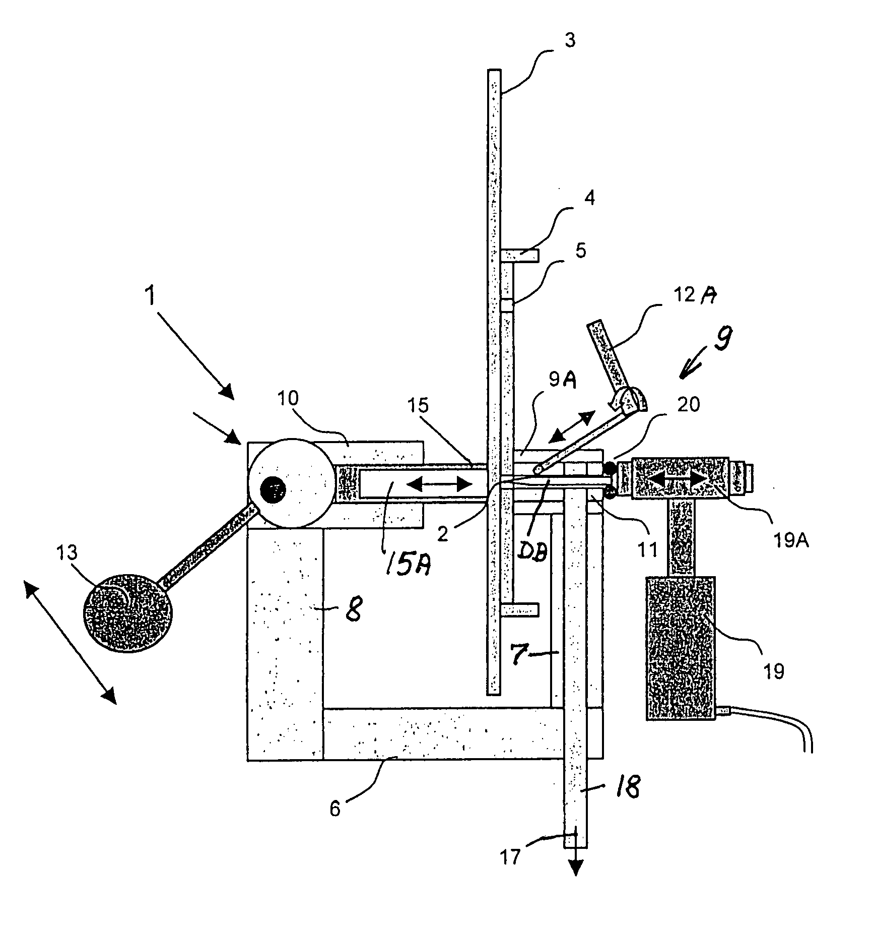
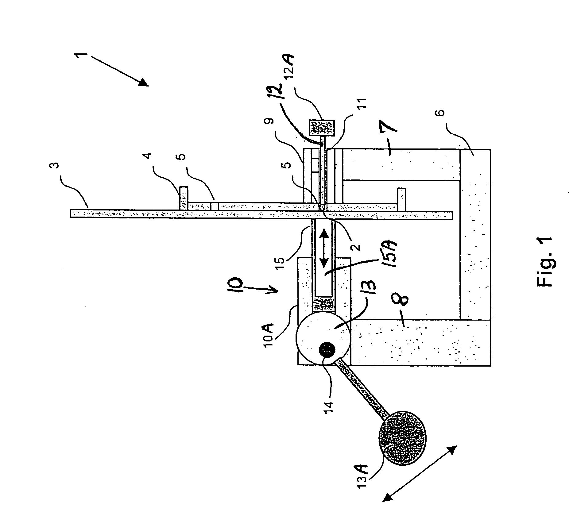
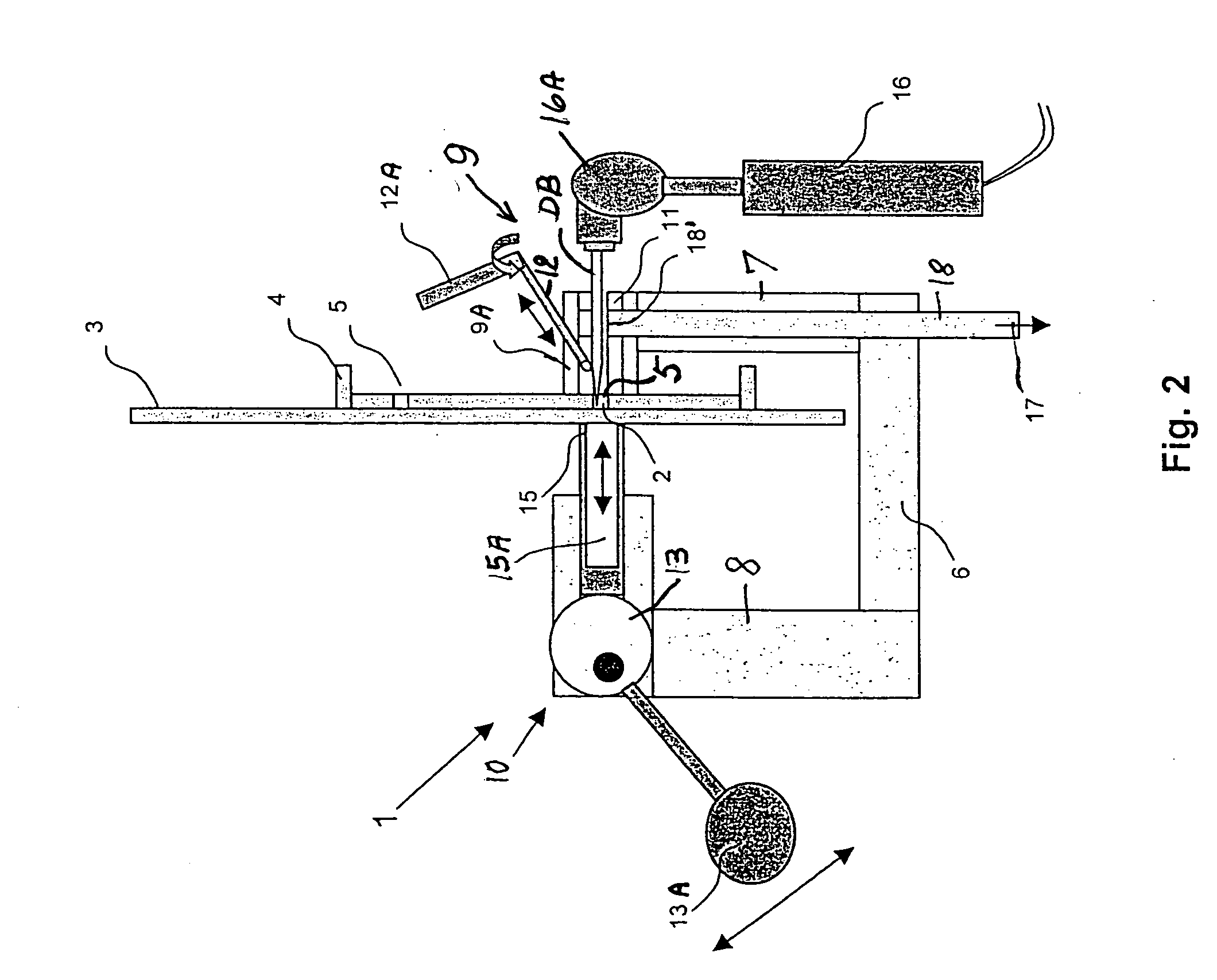
[0022] FIG. 1 shows a schematic side view of the present clamping mechanism for use in combination with handheld tools such as a power drill or similar tools that are used in the assembly of structural components 3, 4. For example a spar 3 is connected with a rib 4 of an aircraft fuselage by riveting which requires the drilling of rivet holes 5 at marked work locations 2 which may be predrilled holes in one of the two components 4, 3.

[0023] The predrilled holes or marked work locations 2 must be accurately aligned with a drill bit DB so that the holes to be drilled through two or more structural components simultaneously are also properly aligned for the riveting operation which requires a snug fit of the rivet shank through the drilled rivet holes. If the rivet holes are not properly aligned with each other it becomes impossible to properly insert a rivet into the rivet holes. To avoid this problem the rivet holes must initially be drilled with the two or more structural components...


PUM

PropertyMeasurementUnit
pressureaaaaaaaaaa
volumeaaaaaaaaaa
weightaaaaaaaaaa

Abstract

The drilling of a hole through at least two structural components in alignment with a predrilled hole or marked location in one of the structural components is facilitated by a clamping mechanism that has a bail with two legs. One leg carries a first clamping section with a guide channel for a centering pin or a drill bit. When the centering pin has served its purpose it is removed from the guide channel which then guides the drill bit. The other leg carries a second clamping section opposite the first clamping section. The second clamping section has a pressure bushing drivable by a clamping drive for clamping the second structural component against the first structural component for drilling a hole through all structural components including through a predrilled hole or for simultaneously drilling all structural components at the marked location. The pressure bushing has a hollow free end forming a cavity.

Description

PRIORITY CLAIM[0001] This application is based on and claims the priority under 35 U.S.C. .sctn.119 of German Patent Application 103 00 202.2, filed on Jan. 8, 2003, the entire disclosure of which is incorporated herein by reference.[0002] The invention relates to a mechanism for clamping at least two structural components to each other to hold these components in a proper position relative to each other for performing work on these components, for example drilling holes.BACKGROUND INFORMATION[0003] In connection with the production, for example, of aircraft structural components a multitude of riveted connections are required, for example for connecting a cross girder or spar to a rib of an aircraft fuselage component. A respective multitude of holes must be drilled through these components for the riveted connections. Conventionally, one of the components to be connected with another component is provided with predrilled holes and these predrilled holes are used as a template for ...

Claims


Application Information

Patent Timeline
Patent Type & Authority Applications(United States)
IPC IPC(8): B23B47/28
CPCB23B47/287B23B2270/12Y10T408/567Y10T408/563Y10T408/553Y10T408/50Y10T408/56245
Inventor OTTEN, JUERGEN
Owner AIRBUS OPERATIONS GMBH
Why Eureka
Try Eureka