Methods and systems for filtering unwanted noise in a material metering machine

a material metering machine and filtering method technology, applied in the field of decimation filters, can solve the problems of many sources of noise, electrical and mechanical, electrical noise, line noise, etc., and achieve the effects of reducing the sampling frequency of the digital signal, reducing the sampling frequency of the signal, and reducing the line noise in the signal

Inactive Publication Date: 2004-07-29
PROCESS CONTROL CORP
View PDF23 Cites 21 Cited by
  • Summary
  • Abstract
  • Description
  • Claims
  • Application Information

AI Technical Summary

Benefits of technology

0012] To achieve the decimation ratio of 120:1, the second decimation element contains a series of filters that each has a particular decimation ratio. For example, the second decimation element can contain three filters that reduce the sampling frequency of the signal from 1200 Hz to 10 Hz in a series of successive steps. The first filter in this example has a decimation ratio of 2:1, thereby reducing the sampling frequency of the signal from 1200 Hz to 600 Hz. The first filter however, has an averaging length of 20, which produces nulls at multiples of 30 Hz. The longer filter length filters out noise introduced by the line voltage at the 60 Hz frequency while providing the decimated signal sampled at 600 Hz.
0013] The second filter in the second decimation element has a decimation ratio of 10:1. The second filter receives the output signal from the first filter at the sampling frequency of 600 Hz and outputs a digital signal sampled at 60 Hz. Instead of using a conventional filter of length 10, the second filter has an averaging length of 20, which produces nulls in the frequency response at multiples of 30 Hz, which further reduce the line noise in the signal while simultaneously creating null at the 60 Hz frequency and its harmonics.
0014] The third filter in the second decimation element has a decimation ratio of 6:1 to reduce the sampling frequency of the digital signal from 60 Hz to 10 Hz. The third filter has a conventional length of 6, which provides the appropriate decimation ratio and produces nulls at integer multiples of 10 Hz to further filter out the line noise at 60 Hz and also at 50 Hz.

Problems solved by technology

However, in this environment there are many sources of noise, both electrical and mechanical.
Another source of electrical noise is line noise, which is the noise introduced into the system by the power supply.

Method used


Image

  • Methods and systems for filtering unwanted noise in a material metering machine
  • Methods and systems for filtering unwanted noise in a material metering machine
  • Methods and systems for filtering unwanted noise in a material metering machine

Examples


Embodiment Construction

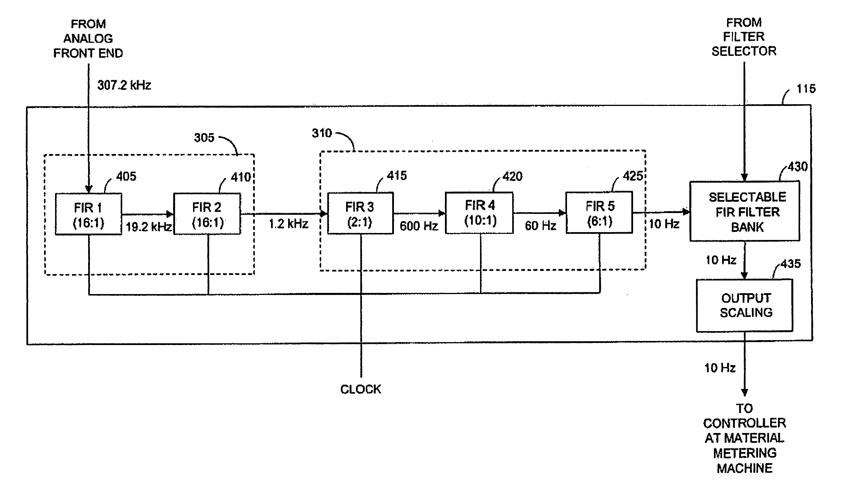
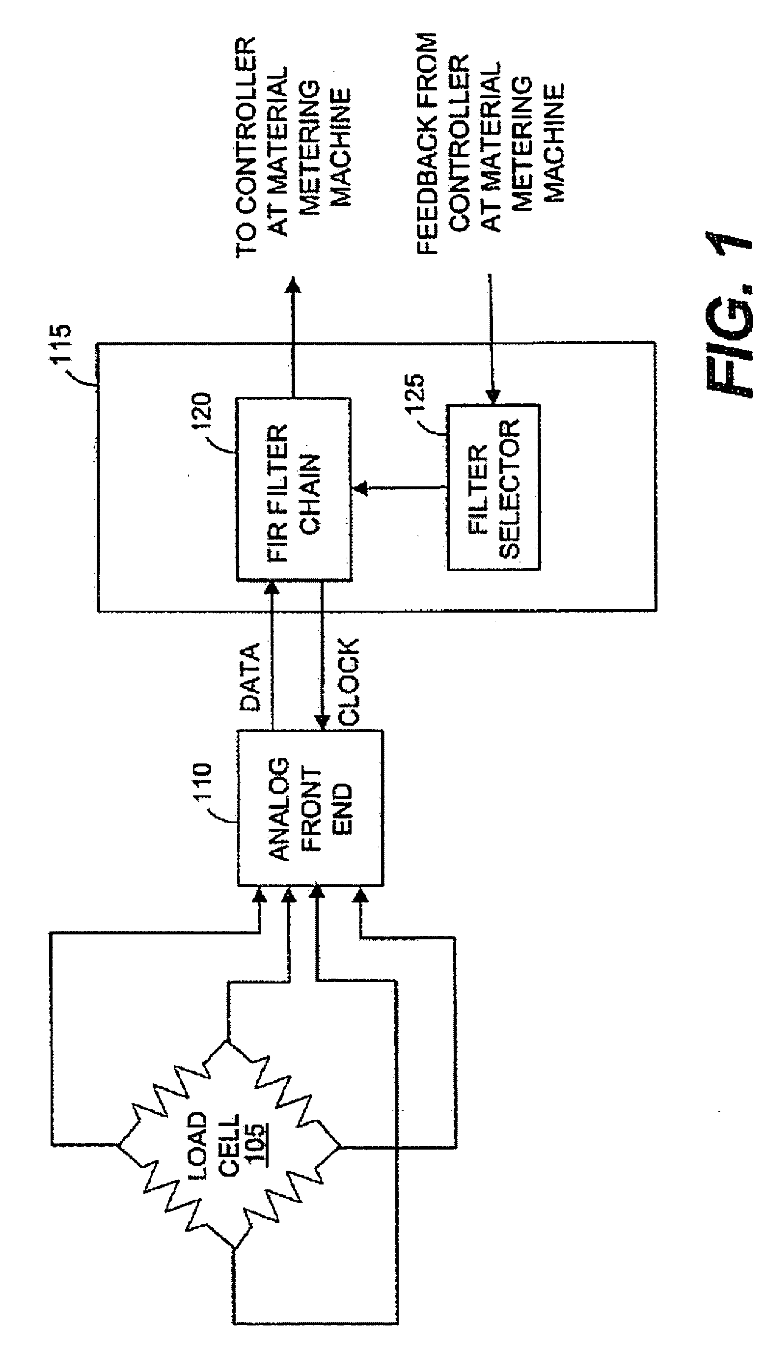
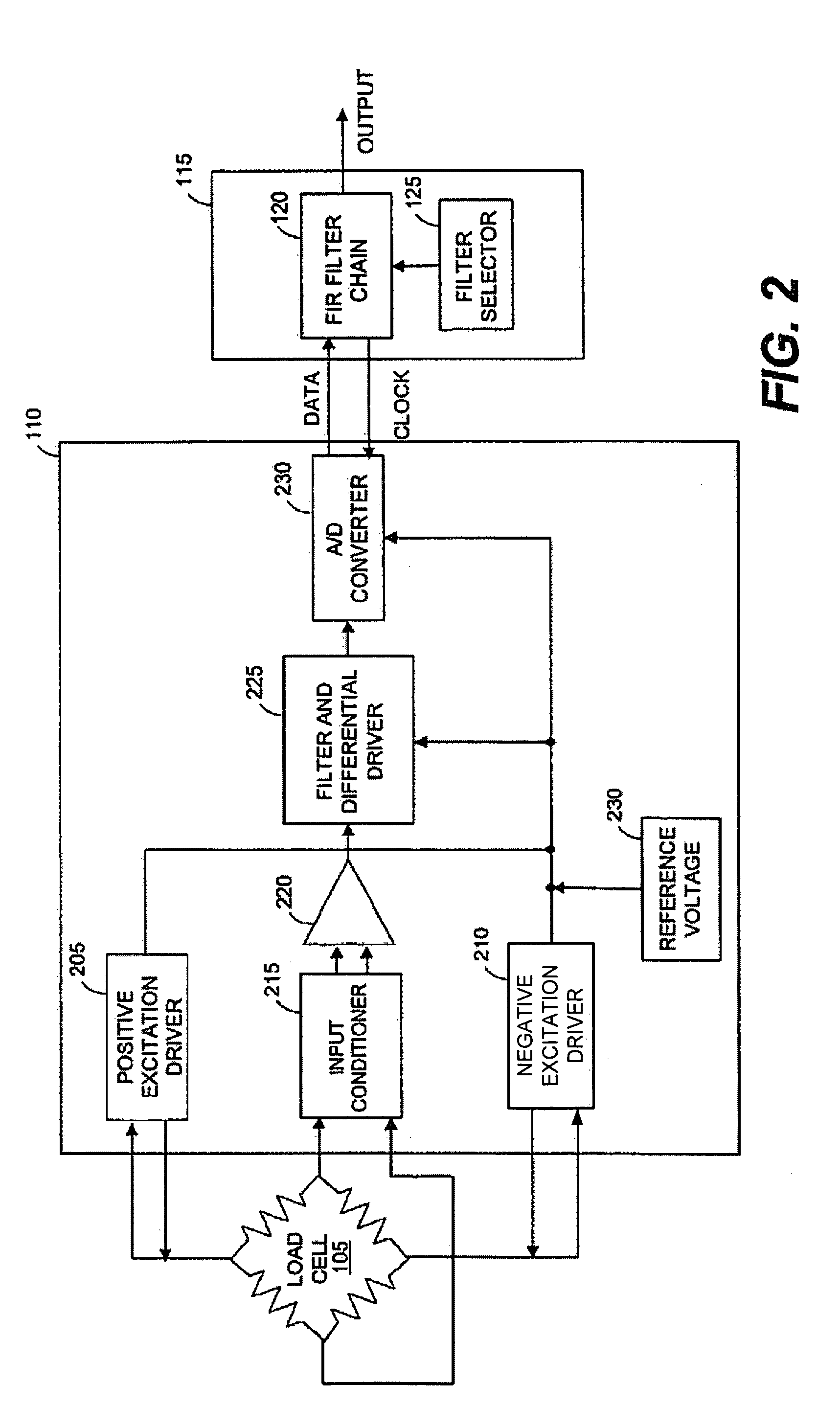
[0029] The operation of the digital filter bank begins when a load cell, also known as a strain gauge, connected to a material metering machine, receives an analog signal that is proportionate to a load placed on the load cell. A positive and negative excitation source drives the load cell, which generates an output voltage, which is proportional to the load. The output signal is a low voltage analog signal and is differential in nature. The low voltage analog signal is then fed to a digital signal processing (DSP) unit, which conditions the signal and converts it from an analog signal to a digital signal. The converted digital signal typically has a high sampling rate, normally about 307.2 kilohertz (kHz), which is within the operating range of the analog-to-digital (A / D) converter

[0030] The digital signal is input to a decimation filter bank that contains a number of individual decimation filters. In the exemplary embodiment, the decimation filter bank contains five (5) finite imp...


PUM


Abstract

Methods and systems for filtering an analog signal sampled at a very high frequency and outputting a digital signal that has a very low sampling frequency to drive a material metering machine. The high frequency digital input signal is input to a first decimation element, which filters out the noise in the signal introduced by an analog-to-digital (A/D) converter and reduces the sampling frequency of the digital signal to a lower sampling frequency of 1200 hertz. The reduced rate digital signal is input into a second decimation element that contains several decimation filters, which reject the 60 hertz line noise and its harmonics while simultaneously reducing the sampling frequency of the digital signal to 10 hertz. The output of the second decimation element is then passed to a bank of selectable filters with sub-hertz cutoff frequencies to remove the machine noise from the material metering machine.

Description

[0001] This application is a continuation of U.S. patent application having Ser. No. 10 / 340,310, filed on Jan. 9, 2003, now issued as U.S. Pat. No. ______.TECHNICAL DESCRIPTION OF THE INVENTION[0002] The present invention is directed to decimation filters, and more particularly to a chain of finite impulse response (FIR) filters for decimating a digital signal with a high sampling frequency, down to a digital signal with a low sampling frequency, having a long word length while simultaneously filtering out line noise introduced by the line voltage.[0003] In the application of material metering machines, load cells are relied upon to provide basic weight measurements. Typically, the material is loaded into a hopper, or a vessel, which is attached to the load cell. As the material passes out of the hopper at the bottom, new material is fed into the top of the hopper. The load cell monitors the weight of the hopper and passes those measurements to a processor which calculates the flow ...

Claims


Application Information

Patent Timeline
Patent Type & Authority Applications(United States)
IPC IPC(8): H03H17/02H03H17/06
CPCH03H17/0664H03H17/025
Inventor THOMSON, MALCOLM G.
Owner PROCESS CONTROL CORP
Why Eureka
Try Eureka