Eureka AIR delivers breakthrough ideas for toughest innovation challenges, trusted by R&D personnel around the world.

Scanning electron microscope

a scanning electron microscope and electron microscope technology, applied in the field of scanning electron microscope, can solve the problems of electron probe blurring, operation of the adapted sem, and the inability to function with the series of differentially pumped diaphragms removed

Inactive Publication Date: 2004-09-09
CARL ZEISS SMT LTD
View PDF22 Cites 21 Cited by
  • Summary
  • Abstract
  • Description
  • Claims
  • Application Information

AI Technical Summary

Benefits of technology

[0010] The reconfigurable microscope provides the advantage that it is capable of being configurable in degrees between functioning as a high-vacuum SEM and an ESEM.
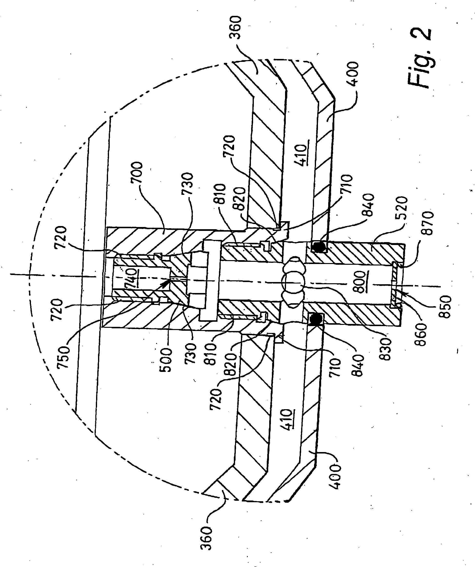
[0028] Moreover, ease of installing and removing the aperture members from the carrier is a practical consideration to render the microscope convenient to use. Hence, the first aperture member preferably includes a slot feature for engaging with a tool when installing or removing the first member from the carrier member. Likewise, the second aperture member preferably comprises a plurality of flats on its exterior surface for engaging with a tool when installing or removing the second member from the carrier member.

Problems solved by technology

Above all, the adapted SEM is not designed to function with its series of differentially pumped diaphragms removed.
Inclusion of the diaphragms and maintaining the sample at elevated pressure introduces problems into operation of the adapted SEM.
Such problems result, for example, from electron scattering in higher-pressure regions surrounding the sample resulting in electron probe blurring.
Moreover, inclusion of differentially pumped diaphragms imposes limitations of longer objective lens working distances and hence increased electron probe spherical aberration.
Furthermore, in extreme cases, differentially pumped diaphragms can be an electron beam semiangle-limiting actor which can render microscope optical alignment problematic and reduce available electron probe current.
The inventors have appreciated that selecting suitable aperture sizes for operating the microscope as an ESEM is not straightforward.
Depths of more than 1.5 mm become difficult to machine whereas depths of less than 0.5 mm provide inadequate gas flow resistance.

Method used


Image

  • Scanning electron microscope
  • Scanning electron microscope
  • Scanning electron microscope

Examples


Embodiment Construction

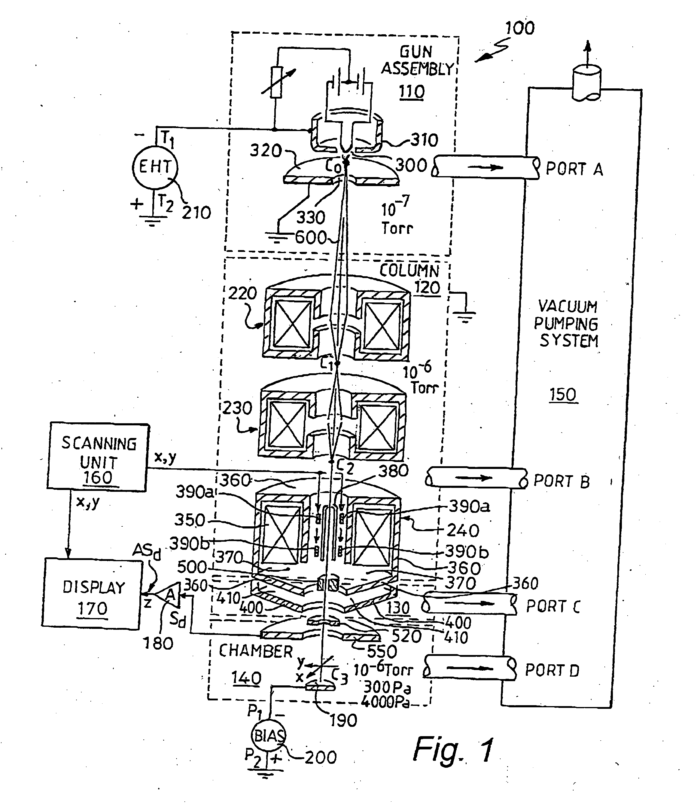
[0040] Conventional SEMs suffer a problem that their samples must be maintained at a high vacuum in the order of 10.sup.-6 Torr pressure or lower. If higher operating pressures are employed, for example 10.sup.-4 Torr, electrical breakdown in their electron guns can occur and electron beam scattering by air molecules along their electron optical columns results in significant broadening of probes generated at their samples. Moreover, reduced operating lifetime of electron emitters employed in their guns arises as trace oxygen in their columns reacts with the emitters.

[0041] Moreover, samples in conventional SEMs require special preparation prior to viewing. Moisture has to be removed from the samples and then a thin coating of conductive material applied thereto, for example a 100 Angstroms thick layer of sputtered aluminium, to prevent sample charging when subjected to electron irradiation. For certain hydrated samples, for example biological tissue samples, such preparation can ma...


PUM


Abstract

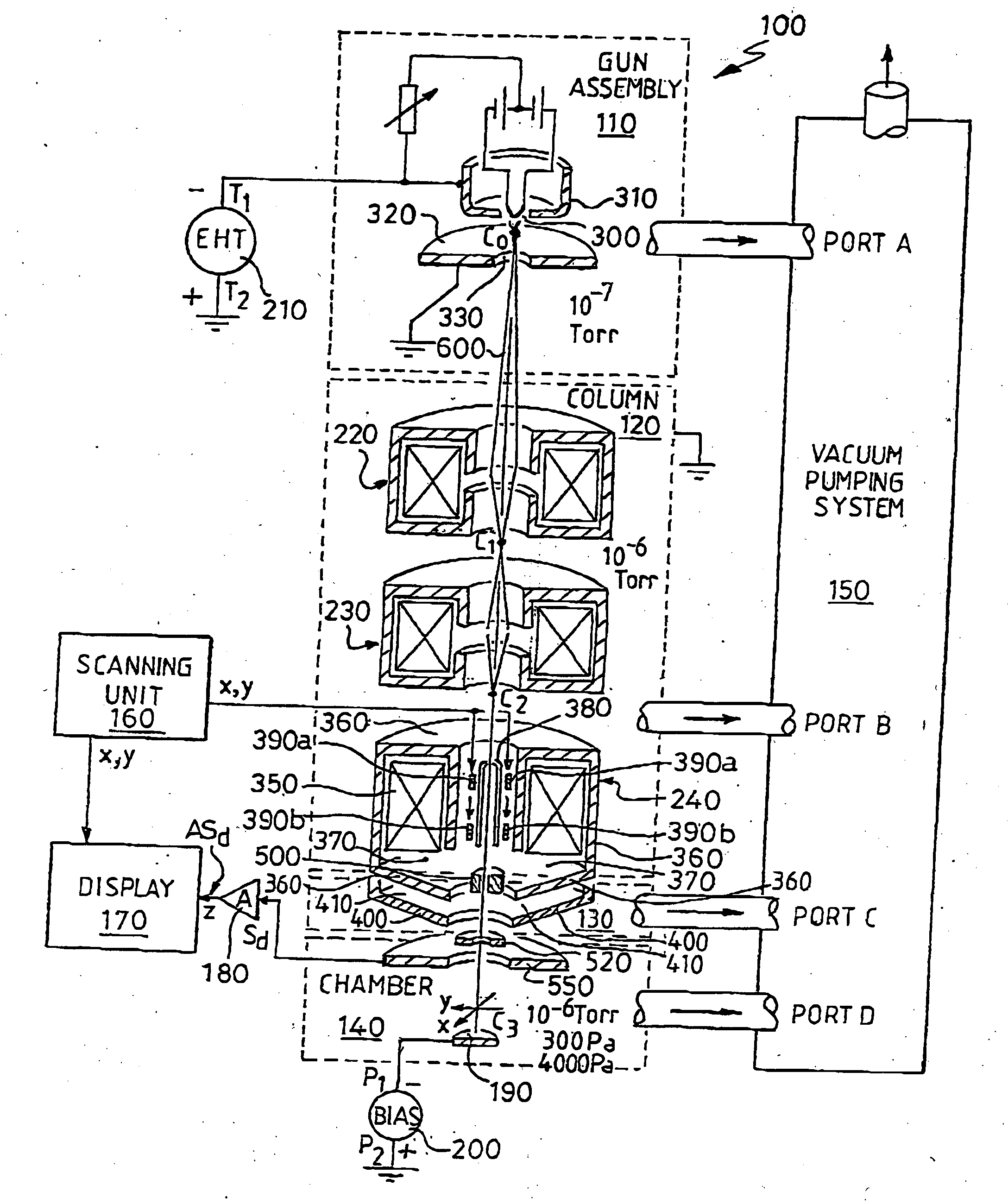
There is provided a reconfigurable scanning electron microscope (RSEM) (100) comprising: (a) a gun assembly (110) and an associated electron optical column (120) for generating an electron beam (600), for demagnifying the electron beam (600) to generate an electron probe (C3) and for scanning the probe (C3) across a sample (190); (b) an electron detector (550) for detecting emissions from the sample (190) in response to scanned electron probe irradiation thereof and for generating a corresponding detected signal (Sd) indicative of the magnitude of the emissions; and (c) a display (170) for receiving the detected signal (Sd) and scanning signals (x, y) indicative of the position of the probe (C3) relative to the sample (190) for generating the image of the sample (190). The RSEM (100) is distinguished in that it further includes aperture bearing members (500, 520), each member (500, 520) including an associated electon-beam transmissive aperture, for at least partially gaseously isolating the gun assembly (110) and the electron optical column (110) from the sample (190), thereby enabling the RSEM (100) to be reconfigurable as a high-vacuum scanning electron microscope and also as an environmental scanning electron microscope, the RSEM (100) being reconfigurable to include no aperture members, one aperture member (500, 750) and a plurality of aperture members (500, 750; 520 850, 860).

Description

[0001] The present invention relates to scanning electron microscopes (SEMs). In particular, but not exclusively, the invention relates to scanning electron microscopes capable of operating as environmental scanning electron microscopes (ESEMs) and also as conventional high-vacuum SEMs.BACKGROUND TO THE INVENTION[0002] ESEMs are distinguished from high-vacuum SEMs in that they are capable of viewing samples maintained at pressures greater than in the order of 100 Pa.[0003] It is known from U.S. Pat. No. 5,250,808 to adapt a conventional scanning electron microscope (SEM) to scan samples maintained at an elevated pressure, for example at an atmospheric pressure of substantially 1000 mBar, 760 Torr, 101.3 kPa. Such an adapted SEM comprises an electron gun for generating an electron beam, one or more electromagnetic lenses with associated electron beam deflectors for demagnifying and scanning the electron beam, a sample chamber for housing a sample to be viewed by scanning the demagnif...

Claims


Application Information

Patent Timeline
IPC IPC(8): H01J37/09H01J37/141H01J37/18H01J37/28H01J37/301
CPCH01J37/28H01J37/301H01J2237/2605H01J2237/2003H01J2237/188
Inventor DEAN, MICHAEL FRANKMARTIN, GILES ADAM EDWARD
Owner CARL ZEISS SMT LTD
Why Eureka
Eureka Blog
Learn More