
Heat spreader module and method of manufacturing same

a heat spreader module and heat dissipation module technology, applied in metal-working apparatuses, solid-state devices, life-saving devices, etc., can solve the problems of increased manufacturing cost, large heat resistance, and high manufacturing cost of heat spreader modules

Inactive Publication Date: 2004-09-30
NGK INSULATORS LTD
View PDF30 Cites 28 Cited by
  • Summary
  • Abstract
  • Description
  • Claims
  • Application Information

AI Technical Summary

Benefits of technology

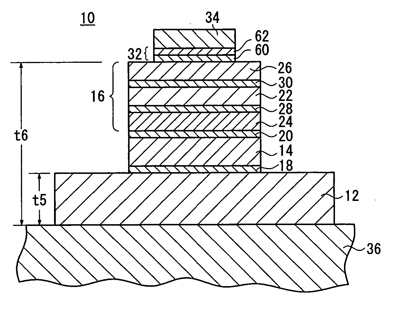
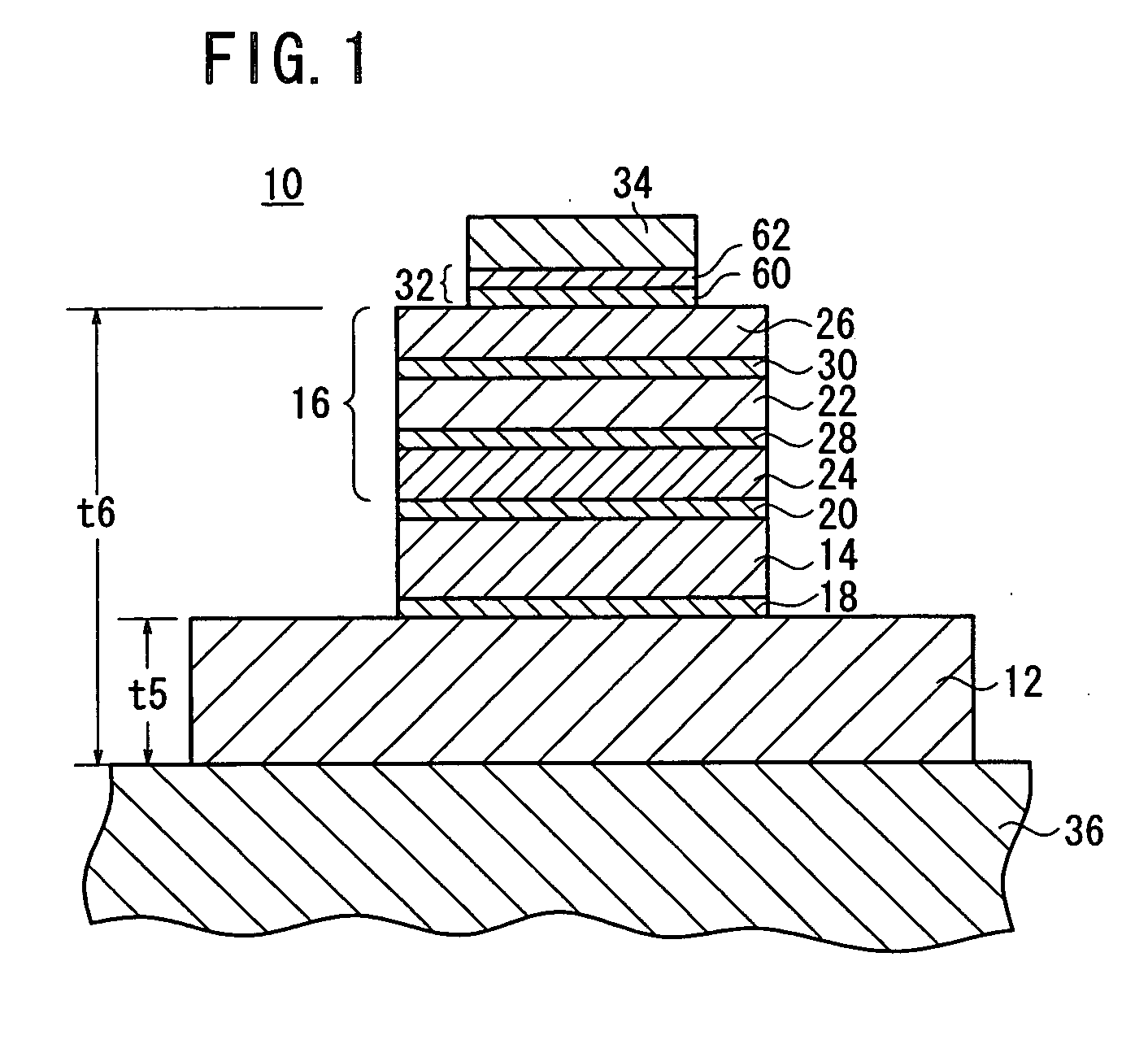
[0012] Since the active hard brazing materials are supplied such that their thickness is in the range from 3 to 20 .mu.m at the time they are melted, when the pedestal, the heat spreader member, the intermediate layer, the insulating board, and the metal plate are joined together under pressure and heat, any amount of the active hard brazing materials that is squeezed out is essentially eliminated or greatly reduced. Therefore, the step of removing any squeezed-out active hard brazing material may be dispensed with, and the manufacturing cost of the heat spreader module may be lowered. Furthermore, alloying of the surface of the metal plate, squeezing-out of the active hard brazing materials onto a side edge of a copper plate used as a buffer layer, and.a reduction in a stress dampening capability due to alloying are suppressed, preventing the heat spreader module from being lowered in quality.
[0022] With the above arrangement, the insulating board and other components that are positioned above and below the metal plate are prevented from cracking. Therefore, the heat spreader module is highly reliable in operation.

Problems solved by technology

However, the solder layers pose a large heat resistance, and the manufacturing cost for the heat spreader module is high because of two joining processes required, i.e., a process of brazing the circuit board and the insulating board to each other and a process of joining the joined assembly to the pedestal.
The need to remove the squeezed active hard brazing material results in an increase in the manufacturing cost.
When the active hard brazing material and the copper plates contact each other, they are alloyed, and the alloyed region has an electric conductivity and a thermal conductivity lower than those of copper, or has durability increased to make the stress dampening capability lower than that of copper, resulting in a reduction in the quality of the heat spreader module.
However, a reduction in the supplied amount of the active hard brazing material tends to cause a shortage of the absolute amount of active elements required to join the components, giving rise to a new problem in that a necessary bonding strength cannot be achieved.

Method used


Image

  • Heat spreader module and method of manufacturing same
  • Heat spreader module and method of manufacturing same
  • Heat spreader module and method of manufacturing same

Examples


Embodiment Construction

;

[0031] FIG. 7A is a perspective view showing an appearance of Comparative Example C1 after its components are joined under pressure;

[0032] FIG. 7B is a perspective view showing an appearance of Comparative Example C2 after its components are joined under pressure;

[0033] FIG. 8A is a perspective view showing an appearance of Inventive Example E1 after its components are joined under pressure;

[0034] FIG. 8B is a perspective view showing an appearance of Inventive Example E2 after its components are joined under pressure;

[0035] FIG. 9A is a cross-sectional view showing an alloyed state of an intermediate layer in Comparative Example C1 after its components are joined under pressure;

[0036] FIG. 9B is a cross-sectional view showing an alloyed state of an intermediate layer in Comparative Example C2 after its components are joined under pressure;

[0037] FIG. 10A is a cross-sectional view showing an alloyed state of an intermediate layer in Inventive Example E1 after its components are joi...


PUM

PropertyMeasurementUnit
Percent by massaaaaaaaaaa
Weightaaaaaaaaaa
Thicknessaaaaaaaaaa

Abstract

A heat spreader module has a pedestal, a heat spreader member joined to the pedestal by a first active hard brazing material, an intermediate layer joined to the heat spreader member by a second active hard brazing material, an insulating board joined to the intermediate layer by a third active hard brazing material, and a circuit board joined to the insulating board by a fourth active hard brazing material. The first through fourth active hard brazing materials are supplied such that the active hard brazing materials have a thickness ranging from 3 to 20 mum when the components of the heat spreader module are joined together under pressure, and contain an active element in an amount ranging from 400 to 1000 mug / cm<2>.

Description

[0001] 1. Field of the Invention:[0002] The present invention relates to a heat spreader module for cooling an IC chip or the like which comprises semiconductors, etc.[0003] 2. Description of the Related Art:[0004] Generally, a heat spreader module for effectively dissipating the heat of a semiconductor device such as an IGBT (Insulated Gate Bipolar Transistor) or the like comprises a circuit board, an insulating board, a heat spreader member (heat diffusion layer), and a pedestal. If necessary, stress dampening layers may be disposed between these components of the heat spreader module. Heretofore, it has been customary to join these components with a solder layer (having a melting point of about 250.degree. C.).[0005] However, the solder layers pose a large heat resistance, and the manufacturing cost for the heat spreader module is high because of two joining processes required, i.e., a process of brazing the circuit board and the insulating board to each other and a process of jo...

Claims


Application Information

Patent Timeline
IPC IPC(8): B23K1/20B23K35/30B23K101/14B23K101/40C04B35/52C04B37/02C22C5/08H01L21/48H01L23/36H01L23/373
CPCB23K35/3006Y10T428/12493C04B35/08C04B35/52C04B35/522C04B35/565C04B37/026C04B2235/407C04B2235/80C04B2235/96C04B2235/9607C04B2237/125C04B2237/34C04B2237/343C04B2237/36C04B2237/363C04B2237/365C04B2237/368C04B2237/407H01L21/4882H01L23/3735H01L2924/0002B32B2311/12H01L2924/00A62B18/025A62B18/10A62B23/025
Inventor ISHIKAWA, TAKAHIROSHINKAI, MASAYUKIMIYAHARA, MAKOTOISHIKAWA, SHUHEINAKAYAMA, NOBUAKIYASUI, SEIJI
Owner NGK INSULATORS LTD
Learn More